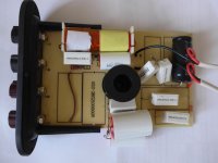
Hi. I have been building some diy speakers. These are a World Designs kit from some years ago. The kit is no longer available. But I managed to get the cabinets from someone, and he gave me instructions on how to make the crossover. Having done this, I am not getting any sound at all. So what I need is someone to show me what I have done wrong with the crossovers.
Maybe I've soldered incorrectly, or done something wrong somewhere. I'm not too sure how to go about getting help with this. I have photos of the crossovers I have made, and a photo of the instructions I was given, which I can post up here. It may not be easy to see clearly what I've done, but we can try that.
Thanks.
Simon
Well seeing what you have would be a start.
To get no sound at all takes a bit of doing 🙂 and so I think starting with basics is the way to go, even down to checking continuity of the drive units and then tracing their path through your crossover.
To get no sound at all takes a bit of doing 🙂 and so I think starting with basics is the way to go, even down to checking continuity of the drive units and then tracing their path through your crossover.
I would make this a priority, so that you don't do something to upset your amplifier. I agree that photos would be good.
This is a picture of the crossover instructions. The pcb is not the right one for this speaker (WD25A), but this is what I was working from.

Hmmm... I can't decipher that tbh. Edit... first image
I'm guessing the terminals at the top are for bi-wiring and that you need to link LF+ and HF+ and also LF- and HF-.
I would concentrate on the bass driver first and try and see what parts and connectivity you have back to the input.
A typical 3 way crossover would have a direct connection from one terminal of the bass driver to the input panel (usually the 'negative') and the other terminal of the driver should have a direct connection via at least one coil back to the other input terminal.
So I would try and work on that basis. There may be a low value series resistor in there as well but see if you have near direct continuity from bass driver to the input panel.
I am not bi-wiring. If you look at first pcb photo, which are his instructions, it shows how to link for single or bi wire. So I have linked for single wire.
Last edited:
See if you can relate the crossover scheme to something like this. The coils should be very low resistance and so the bass driver should appear as if it is connected to the amplifier if you do a resistance check. This is just a typical generic type crossover.
Also check there is no measurable short between the input terminals of your crossover.
Good luck 🙂 I'm sure the others will pick this up.
Also check there is no measurable short between the input terminals of your crossover.
Good luck 🙂 I'm sure the others will pick this up.
Attachments

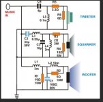
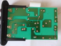
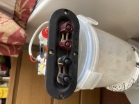
Photo of other side.
You do need to solder those input terminals to the boards...
Are there any components where I need to solder both sides of the pcb? Sometimes you need to make sure the solder has flowed right through. I'm also not 100% sure about the links he refers to, and wether I have done those correctly.
I will try a continuity test.
I will try a continuity test.
So in the first photo, which is the instructions, I have linked where it says 'single wire'. Does that not connect the terminals?
These need to be soldered to the pads.
The board is just single sided and so you only solder on the copper side. Try and work through with a meter checking the continuity and also do the check across the input panel sockets (once soldered) to make sure you haven't inadvertently got a short across the amplifier.
I'll look in later 🙂
The board is just single sided and so you only solder on the copper side. Try and work through with a meter checking the continuity and also do the check across the input panel sockets (once soldered) to make sure you haven't inadvertently got a short across the amplifier.
I'll look in later 🙂
Attachments
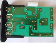
So what your saying is, I need to connect the actual speaker terminal to the hf and lf on the boards? So a stupid error, and exactly what I was hoping someone would point out to me here?
From what I see you need to to:
1/ Solder all those tabs to the board.
2/ Link the sockets as shown in post #10 (that is normally done externally with links as it is a user selectable choice).
3/ Connect the drive units to the marked holes on the board.
4/ Do a quick check to make sure there is no direct short showing across the inputs. You should actually read the woofer voice coil resistance plus a little extra of the coils. So a few ohms.
If you can not read the woofer resistance across the input terminals then trace the connectivity from the inputs to the speaker terminals.
3/ Wire the speakers to all the marked holes on the board.
 I thought they would have to be.
So work through the other checks tracing the circuit as you go.

- Home
- Loudspeakers
- Multi-Way
- DIY crossover help needed