precision resistors, approaching calibration lab standards level are thermally cycled/aged by the manu to accelerate stress relaxation, reduce value drift after the customer gets the device
so EE do actually know about these effects - and when the product performance specs demands and customer is willing to pay for the cost they do it
so EE do actually know about these effects - and when the product performance specs demands and customer is willing to pay for the cost they do it
@ The Gimp
What cost? What equipment? All they have to do is imply that they are being "burned in". How will the silly audiophool ever know the difference? Expectation factor.
What cost? What equipment? All they have to do is imply that they are being "burned in". How will the silly audiophool ever know the difference? Expectation factor.
No it won't. Cap stored energy is 0.5 C V^2, so the stored energy varies as a sine wave at twice the signal frequency i.e. one harmonic (the 2nd). So what? It is what caps are supposed to do. A loosely constructed cap might have problems, not due to stored energy but electrostatic forces. Decent commercial caps should be fine.abstract said:Even if the driving signal is a pure sine wave, if there's no DC bias, the amount of stored energy will resemble a rectified sine wave with lots of harmonics.
In engineering, intuition needs to be kept informed by facts as otherwise it will lead you astray.
If they were to burn them in for days, wouldn't it be more like thousands or tens of thousands of caps at a time?
I guess it boils down to how many caps do they sell per year.
If they are not a listed company there is no prospectus available.
Has anyone ever seen numbers for say Auricap production?
I guess it boils down to how many caps do they sell per year.
If they are not a listed company there is no prospectus available.
Has anyone ever seen numbers for say Auricap production?
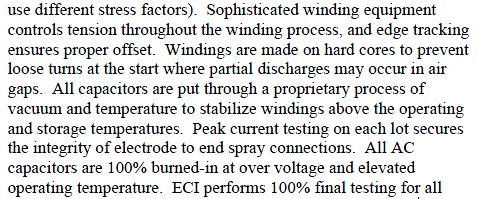
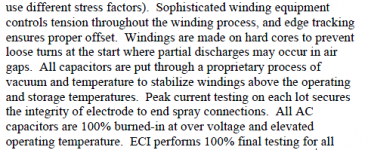
and caps do get wound tight, burned in too - where performance demands - like high power "pollution factor" rated industrial motor run caps
http://www.apec-conf.org/wp-content/uploads/2013/09/is1.3.1.pdf
http://www.apec-conf.org/wp-content/uploads/2013/09/is1.3.1.pdf
Attachments
I'm sorry, I'm not following this.
Apply a voltage across a capacitor and there'll be some force pulling the plates together. I did some net searching and found that the typical thickness of the film inside a capacitor could be around 1 micron. With some calculations I estimated that for a 1uF cap it could be 100 newtons at 10V, which is quite a lot of weight squishing those air bubbles repeatedly.
If the OP wants to test the burn-in for us, here's my suggestion 😀 :
Get 2 identical capacitors.
Do the burn-in on 1 of them* and store the other one.
*Pass 100 hours of loud music through the cap, using a 10W 8 ohm or 4 ohm resistor in series. At the start, keep turning up the volume until the resistor gets warm, and check up on it every now and then to make sure nothing is catching on fire.
After the 100 hours, ask a friend to label them so that only they know which one is which. And then do some listening tests.
and caps do get wound tight, burned in too - where performance demands - like high power "pollution factor" rated industrial motor run caps
http://www.apec-conf.org/wp-content/uploads/2013/09/is1.3.1.pdf
So they over volt them and at elevated temps? Sounds more like trying to make them fail. I'd prefer a new cap that hasn't been abused 😉
With some calculations I estimated that for a 1uF cap it could be 100 newtons at 10V, which is quite a lot of weight squishing those air bubbles repeatedly.
First, in any quality cap from a major manufacturer, there are no "air bubbles." Second, the "weight" (I think you mean "force") is spread over a pretty large area. The relevant mechanical parameter for the dielectric is compressive modulus. Third, you might want to think about what situations would result in 10VAC across a 1u cap. There aren't many, and for any audio use, they're at low frequencies.
Just using everyday terms.First, in any quality cap from a major manufacturer, there are no "air bubbles." Second, the "weight" (I think you mean "force")
And then rolled up or stacked, so every layer adds a little bit of pressure to the one beneath it.is spread over a pretty large area.
I only suggested loud music as a test signal, and 10Vpk into an 8 ohm load is 6.25W (assuming rms), or 10VAC: 12.5W.The relevant mechanical parameter for the dielectric is compressive modulus. Third, you might want to think about what situations would result in 10VAC across a 1u cap. There aren't many, and for any audio use, they're at low frequencies.
1st order high pass filters for tweeters get exposed to the full music signal like I described so I say it's not that unusual.
Just using everyday terms.
And then rolled up or stacked, so every layer adds a little bit of pressure to the one beneath it.
I only suggested loud music as a test signal, and 10Vpk into an 8 ohm load is 6.25W (assuming rms), or 10VAC: 12.5W.
1st order high pass filters for tweeters get exposed to the full music signal like I described so I say it's not that unusual.
Using "everyday terms" in engineering or physics discussions can easily lead one astray.
Remember that it's not the load voltage that's important, it's the voltage across the cap.
I absolutely do not understand the physics of what you're trying to say about the rolls and stacks. Perhaps there's some terms (mathematically speaking) in the description of the mechanics that you're missing?
OK, let's just say we're just talking about the output voltage from the amp. At HF most of it will be across the resistor, and at low F most will be across the cap. Situation normal. A lower valued resistor would increase the high pass cut-off, but also put more pressure on the amplifier.Using "everyday terms" in engineering or physics discussions can easily lead one astray.
Remember that it's not the load voltage that's important, it's the voltage across the cap.
I'm not sure how to describe it. Imagine you're tying string around something, even if you make each turn very light, each turn will add a bit of pressure.I absolutely do not understand the physics of what you're trying to say about the rolls and stacks. Perhaps there's some terms (mathematically speaking) in the description of the mechanics that you're missing?
I'm not sure how to describe it.
It may help to draw some pictures. Use a stack for simplification. Consider the charges on each foil. Note which forces cancel.
I think that will clear things up for you.
It may help to draw some pictures. Use a stack for simplification. Consider the charges on each foil. Note which forces cancel.
I think that will clear things up for you.
Dang, you're right. I must be tired today. OK so those air bubbles from the sloppy boutique manufacturing process are unlikely to get severely affected after all. That's not to say that there won't be other stresses due to movement. That still leaves mechanical fatiguing of the casing as something people can play around with to see if they hear any difference. I'd still try to linearize those forces with a DC offset. For passive XOs that would mean playing around with bridged amps, or focusing on 3rd order XOs where the middle filter element is connected to some offset.
Because physical capacitors are objects, made by man in various processes, they won't be 'perfect' - some of the myriads of characteristics will vary in subtle ways, depending on everything, and some of that may have audible effects. Personally, I 'thrash' circuits for extended periods, electrically speaking, before taking them seriously in terms of listening qualities, because I have found that makes a, usually positive, difference. How much of that is due to capacitor burn-in, or conditioning is how I would call it, is not "perfectly" clear - however, the long term experience is that this approach always has to be used, for a cold start situation, for the best sound.
The goal would be 'ideal' sound, say, after 5 minutes from switch-on, and not to vary from that - every capacitor in the circuit could be part of the 'problem' if that doesn't happen, a painful and laborious process to properly test ...
The goal would be 'ideal' sound, say, after 5 minutes from switch-on, and not to vary from that - every capacitor in the circuit could be part of the 'problem' if that doesn't happen, a painful and laborious process to properly test ...
Last edited:
....alternatively, you are thrashing your ears which become accustomed the sound.
This explanation has the advantage over yours that it aligns with (and more importantly, doesn't contradict) all the known science on the subject - physics, biomechanics, psychology, the lot.
This explanation has the advantage over yours that it aligns with (and more importantly, doesn't contradict) all the known science on the subject - physics, biomechanics, psychology, the lot.
and caps do get wound tight, burned in too - where performance demands - like high power "pollution factor" rated industrial motor run caps
http://www.apec-conf.org/wp-content/uploads/2013/09/is1.3.1.pdf
Burn in not break in, there is a difference, and this thread is now erroneously using burn in instead of break in. Burn in is to stress and weed out early failures, this is common practice for high rel electronics, it is not to change the device parameters.
Sometimes, I use signals which have nothing to with music, 😉- and don't sit around, listening closely to it. At one stage I was using the MATT track - Google it - which was very effective for stabilising an obvious, spurious resonance in one speaker; and another time an 18kHz sine wave.....alternatively, you are thrashing your ears which become accustomed the sound.
There are no contradictions - audio systems have embedded in them many so-so parts, like an old car does, 🙂, and just like the latter a good warmup can do wonders for it ... 😉
true, some components have a significant temperature coefficient effect.
But again, as always, you are making claims for your findings that are not supported by your testing technique.
Additionally, a compentently designed system owill ensure that critical components are not adversely impacted by temperature change, and that any that are have a compensation system.
In short, if a system is so affected by operating temperature that you are able to identify the drift merely by listening to the system, its a crap system, or possibly in need of repair.
Again, end of this discussion for me. I don't intend to try and aggregate you to a change of mind when you are so clearly enjoying the process you are involved in!
That's fine ... my goal is to have a "competently designed system" providing music for me in any situation, and clearly real life audio falls well short of doing that, most of time. I aim to troubleshoot the failings, and changes in behaviour over time are a guide to where the issues are, some of which may be temperature related
Apply a voltage across a capacitor and there'll be some force pulling the plates together. I did some net searching and found that the typical thickness of the film inside a capacitor could be around 1 micron. With some calculations I estimated that for a 1uF cap it could be 100 newtons at 10V, which is quite a lot of weight squishing those air bubbles repeatedly.
If the OP wants to test the burn-in for us, here's my suggestion 😀 :
Get 2 identical capacitors.
Do the burn-in on 1 of them* and store the other one.
*Pass 100 hours of loud music through the cap, using a 10W 8 ohm or 4 ohm resistor in series. At the start, keep turning up the volume until the resistor gets warm, and check up on it every now and then to make sure nothing is catching on fire.
After the 100 hours, ask a friend to label them so that only they know which one is which. And then do some listening tests.
There is a test report from the AES from a major cap manu who researched cap vibration from magneto-striction and they found about 1 molecule width of excursion. The thing most forget is that within the cap most forces between windings, due to construction, largely cancel. This is a non-issue.
jan
- Status
- Not open for further replies.
- Home
- Member Areas
- The Lounge
- DIY Capacitor Burner.