OK GM, here it is, Bon Appetit: 😀
-------------------------------------------------------
Filter 'LPAmp' | second order Butterworth lowpass
fo=0,15kHz | Plate amp variable freq
{ Q=sqrt(0.5);
b0=1;
a2=1; a1=1/Q; a0=1; }
Filter 'LPcomp' | second order Butterworth lowpass
fo=0,15kHz | Computer LP cutoff for LFE
{ Q=sqrt(0.5);
b0=1;
a2=1; a1=1/Q; a0=1; }
Filter 'XMAXprot' | second order Butterworth HIpass
fo=0,025kHz | Rumble filter in Plate Amp
{ so=1; |Scale factor (set to 1, so fo=lower cutoff)
b2=1/sqr(so);
a2=b2; a1=sqrt(2)/so; a0=1; }
Def_Reflector BottomCorner
Left=75.0cm Bottom=75.0cm Right=10.0cm
HAngle=90.0° VAngle=45.0°
Def_Driver 'Driver'
Sd=218.00cm2
Bl=7.60Tm
Cms=1.21E-03m/N
Rms=2.21Ns/m
fs=27.9192Hz |Mmd = 25.00g not recognised by AkAbak, fs calculated and used instead
Le=0.60mH
Re=6.20ohm
ExpoLe=1
System 'System'
Driver Def='Driver''Driver'
Node=1=0=300=200
Enclosure 'BackChamber'
Node=300
Vb=0,027m3
Waveguide 'Totdrvr'
Node=199=200
WTh=0,22m
HTh=0,065m
WMo=0,22m
HMo=0,08m
Len=0,15m
Conical
Waveguide 'EersteCon'
Node=200=201
WTh=0,22m
HTh=0,08m
WMo=0,22m
HMo=0,12m
Len=0,535m
Conical
Vf=0,001m3 | Onder Cone
AcouMass 'Ma1a' Node=201=202
Ma={1.85/0.12} | 90° bend Ma=1.85/WD
AcouMass 'Ma1b' Node=202=203
Ma={1.85/0.135} | 90° bend Ma=1.85/WD
Waveguide 'TweedeCon'
Node=203=204
WTh=0,22m
HTh=0,135m
WMo=0,22m
HMo=0,185m
Len=0,52m
Conical
AcouMass 'Ma2a' Node=204=205
Ma={1.85/0.185} | 90° bend Ma=1.85/WD
Waveguide 'DerdeCon'
Node=205=206
WTh=0,22m
HTh=0,22m
WMo=0,22m
HMo=0,23m
Len=0,05m
Conical
AcouMass 'Ma3a' Node=206=207
Ma={1.85/0.23} | 90° bend Ma=1.85/WD
Waveguide 'LaatsteCon'
Node=207=208
WTh=0,22m
HTh=0,23m
WMo=0,22m
HMo=0,475m
Len=0,425m
Conical
Duct 'Mond"
Node=208=209
WD=0,295m
HD=0,295m
Len=0,01m
Waveguide 'External'
Node=209=210
WTh=0,295m
HTh=0,295m
WMo=0,1m
HMo=1,5m
Len=0,75m
Conical
Radiator 'Horn mouth'
Node=210
SD=1520cm2
WEdge=22cm HEdge=22cm Reflection
---------------------------------------------------
You'll notice the active filtering (amp+computer) and the rumble filter of the amp.
BTW, I think both programs assume totally rigid boundaries, so the difference should be elsewhere.
I found out so far that the Radiator Element (10cm*150cm slit between wall and bDEAP) is actually in full contact with the wall, while the above script has it floating 75cm and 22cm away from it. Changeing this to 1cm distances gives 30Hz@100dB till 90Hz around 112dB. Still 5dB short of HornResp @30Hz, but if i remember correctly, HornResp just assumes radiation into 1/8th space, while in this case AkAbak correctly assumes it radiates about 75cm *away* from the corner. Unfortunately I can't find a way to make AkAbak point the Radiator into the corner ( Check out Def > Def_Reflector ... and click "Bottom Corner" and move the sliders), but I'm sure if it could be done, the extra 5dB loading in the lower octave would pop up.
I'll try to explain how i think hornResp's SPL curve would be attained:
Press your wrist against the wall and your fingers into the corner fold. Then move back a little bit and tilt your fingers so they are about 1/2 inch away from the fold, keeping your wrist against the wall. The external airpath starts then at your wrist and ends in your fingers, exactly into the corner. This is what Hornresp models with the extra external segment included.
If you keep your wrist into the fold and do the same with your fingers, the external airpath ends *away* from the corner fold. This is what AkAbak models here and I think this is why there is less sensitivity that expected from HornResp.
Re: AkAbak Vs HornResp in Corners
Hi Cordraconis,
I notice that you have posted an AkAbak pressure chart. If you wish to compare AkAbak against Hornresp, make sure that you use the acoustic power chart. You will then find that the results of the two programs are identical, for equivalent specification systems. I am not sure that AkAbak treats corner loading correctly, though.
I see that you are putting the Hornresp AkAbak script file export tool to good use 🙂.
Kind regards,
David
Cordraconis said:Either one of the programs is very optimistic/pessimistic about corner loading or else I forgot something in AkAbak which I think not ...
Hi Cordraconis,
I notice that you have posted an AkAbak pressure chart. If you wish to compare AkAbak against Hornresp, make sure that you use the acoustic power chart. You will then find that the results of the two programs are identical, for equivalent specification systems. I am not sure that AkAbak treats corner loading correctly, though.
I see that you are putting the Hornresp AkAbak script file export tool to good use 🙂.
Kind regards,
David
Re: Re: AkAbak Vs HornResp in Corners
Hi Cordraconis,
Just to elaborate:
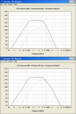
At very low frequencies there is a theoretical +6dB improvement in SPL response each time the solid radiation angle is halved. 3dB is due to improved acoustical loading conditions (enabling twice the power to be radiated), and the other 3dB is due to the doubled power radiating into half the space. Going from free space to eighth space therefore gives an 18dB increase overall.
At very high frequencies (assuming constant directivity) there is only a +3dB enhancement - the acoustical loading conditions do not change when the solid radiation angle is halved. Going from free space to eighth space therefore gives a 9dB increase overall.
With a directional horn, at very high frequencies there is no change in the on-axis SPL as the solid angle is halved. This is because the sound radiates in a "beam" fully contained within the defining solid angle boundary.
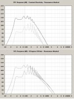
The top chart in the attachment shows the constant directivity response for a simple exponential horn. The black trace is the eighth space (corner) response and the grey trace is the free space response. The 18dB difference at low frequencies and 9dB difference at high frequencies can be clearly seen.
The bottom chart shows the on-axis directivity response for the same horn. Once again the black trace is the eighth space (corner) response and the grey trace is the free space response. The 18dB difference at low frequencies and 0dB difference at high frequencies can be clearly seen.
Does AkAbak give the same sort of results?
Kind regards,
David
David McBean said:I am not sure that AkAbak treats corner loading correctly, though.
Hi Cordraconis,
Just to elaborate:
At very low frequencies there is a theoretical +6dB improvement in SPL response each time the solid radiation angle is halved. 3dB is due to improved acoustical loading conditions (enabling twice the power to be radiated), and the other 3dB is due to the doubled power radiating into half the space. Going from free space to eighth space therefore gives an 18dB increase overall.
At very high frequencies (assuming constant directivity) there is only a +3dB enhancement - the acoustical loading conditions do not change when the solid radiation angle is halved. Going from free space to eighth space therefore gives a 9dB increase overall.
With a directional horn, at very high frequencies there is no change in the on-axis SPL as the solid angle is halved. This is because the sound radiates in a "beam" fully contained within the defining solid angle boundary.
The top chart in the attachment shows the constant directivity response for a simple exponential horn. The black trace is the eighth space (corner) response and the grey trace is the free space response. The 18dB difference at low frequencies and 9dB difference at high frequencies can be clearly seen.
The bottom chart shows the on-axis directivity response for the same horn. Once again the black trace is the eighth space (corner) response and the grey trace is the free space response. The 18dB difference at low frequencies and 0dB difference at high frequencies can be clearly seen.
Does AkAbak give the same sort of results?
Kind regards,
David
Attachments
Thank you for the graphs Mr. McBean,
Before I read your post however, I had stripped all the waveguides/horns in both AkAbak and HornResp 17.20 and kept only the back chamber and the corner loading.
Both your program and AkAbak had the same sensitivity and SPL curve. The -3dB point was 55Hz and AkAbak was 1.5dB more sensitive than HornResp at that frequency but that is hardly something to speak about imho.
Edit: The directivity tool in HornResp was greyed out when I quickly tried it, and when I went to AkAbak and did a pressure curve at 3 different listening angles the curves were completely identical. I'll have to go soon and I'll try wrapping my mind around it later with the latest version this weekend.
So far the 30Hz point is still +-12dB down in AkAbak (wrt 80Hz) and only 5dB in HornResp.
For people who want to design a bDEAP too:
One thing that struck my yesterday on the bus to work, is that the horn mouth of the external path is determined by the mouth area, and since the cabineth dimensions are known, the distance from the wall is found. However, these distance-rules ALSO apply to the throat!!! With my 295mm squared throat, the distance must be 140mm from the wall in order to not choke off the cabinet exit!!!
So the external airpath flare rate will be about 33Hz as the horn must be placed further from the wall!
A second thing that struck me: As you see from the design drawing, there is still some room to make a larger cabinet exit (=throat area of the external path) and thereby increasing the flare rate of the last internal horn section. This makes the horn tuning higher and adds more HF output, less ripples and some more sensitivity overall from the larger external mouth area.
Since I/we are now wrestling with the LF sensitivity, this point is a bit moot but maybe applicable to someone else's design.
Re: Re: Re: AkAbak Vs HornResp in Corners
Hmm, I view it as the corner yielding a four square mirror, so one driver at the floor corner junction Vs half space = four acoustic radiators, ergo for a given excursion there's a theoretical +12.04 dB increase, which is what Hornresp and other programs I have ~predict, but for me it's so far been a 'wishful thinking' number since the best I've measured has only been ~half this. 🙁
GM
David McBean said:
At very low frequencies there is a theoretical +6dB improvement in SPL response each time the solid radiation angle is halved.
Hmm, I view it as the corner yielding a four square mirror, so one driver at the floor corner junction Vs half space = four acoustic radiators, ergo for a given excursion there's a theoretical +12.04 dB increase, which is what Hornresp and other programs I have ~predict, but for me it's so far been a 'wishful thinking' number since the best I've measured has only been ~half this. 🙁
GM
GM said:but for me it's so far been a 'wishful thinking' number since the best I've measured has only been ~half this. 🙁
Hi GM,
I did say "theoretical" - as you know, in practice very few things are perfect 🙂.
BTW, if you are still having difficulty reading the Hornresp Help file, another solution occurred to me that may make it easier for you. Simply take screenprints of the individual Help pages, copy them into a Word document and set the zoom factor to 150% or higher.
Kind regards,
David
Cordraconis said:The directivity tool in HornResp was greyed out when I quickly tried it
Hi Cordraconis,
The Hornresp directivity tool does not work with direct radiators 🙂.
Kind regards,
David
Re: Re: Re: AkAbak Vs HornResp in Corners
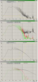
Once I figured that out, I've done the comparison with a single 300cm long conical segment from 180 till 2213 cm^2
I couldn't find out how to overlay Free Space Vs Corner loading responses with 0° off-axis in HornResp, so Cptn Photoshop came to the rescue.
Sorry for the delay.
Honestly, it doesn't seem such a clear-cut case as I tought. The ripples make it more difficult to see. Should I compare with the peaks or the troughs?
AkAbak makes the whole curve smoother and shifts the sensitivity up. If there is some LF lift, it is not so pronounced.
HornResp mainly shifts the sensitivity up and there is some LF gain, but the ripples are more obvious.
The directivity tool works with a single segment straight horn so that is why my bDEAP model (with the added external conical segment) had it greyed out. Ditto for the AkAbak directivity.David McBean said:
At very low frequencies there is a theoretical +6dB improvement in SPL response each time the solid radiation angle is halved.
At very high frequencies (assuming constant directivity) there is only a +3dB enhancement
...
Does AkAbak give the same sort of results?
Once I figured that out, I've done the comparison with a single 300cm long conical segment from 180 till 2213 cm^2
I couldn't find out how to overlay Free Space Vs Corner loading responses with 0° off-axis in HornResp, so Cptn Photoshop came to the rescue.
Sorry for the delay.
Honestly, it doesn't seem such a clear-cut case as I tought. The ripples make it more difficult to see. Should I compare with the peaks or the troughs?
AkAbak makes the whole curve smoother and shifts the sensitivity up. If there is some LF lift, it is not so pronounced.
HornResp mainly shifts the sensitivity up and there is some LF gain, but the ripples are more obvious.
Attachments
Re: Re: Re: Re: AkAbak Vs HornResp in Corners
Hi Cordraconis,
Many thanks for the feedback. I am not sure why Hornresp and AkAbak results turn out to be so different in this case.
1. Calculate the Free Space 0° off-axis response, then press Ctrl+C or right-click on the SPL chart and click "Capture current results".
2. Calculate the Corner 0° off-axis response, then select Tools > Compare Captured or press the F4 function key.
I would compare the peaks.
Kind regards,
David
Hi Cordraconis,
Many thanks for the feedback. I am not sure why Hornresp and AkAbak results turn out to be so different in this case.
Cordraconis said:I couldn't find out how to overlay Free Space Vs Corner loading responses with 0° off-axis in HornResp.
1. Calculate the Free Space 0° off-axis response, then press Ctrl+C or right-click on the SPL chart and click "Capture current results".
2. Calculate the Corner 0° off-axis response, then select Tools > Compare Captured or press the F4 function key.
Cordraconis said:Should I compare with the peaks or the troughs?
I would compare the peaks.
Kind regards,
David
Hm, didin't realize it has been so long since I posted about my progress, or the lack of it. 🙂
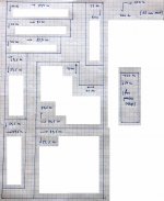
My next step was to make the cut plan to squeeze as much panels as possible out of a 244cm*122cm MDF panel (18mm thick)
For MJK - who was interested in my plans to use them with a 8" car subwoofer - I took a snapshot of it so he can beat me to the punch if he gets his hands on some MDF before I do:
Sorry for the white rectangles but i tried to remove as much non essential things out of the pic for compression reasons. It should be clear how to proceed. The separate 61*22cm panel will come from a MDF leftover I had from my previous sub, so I'll only have to buy one large panel for the rest.
I'll try tomorrow to send an email to the AkAbak authors to ask for the discrepancy between HornResp and AkAbak 's LF loading in corners, but since I'm using the free Version 1, I doubt the'll give feedback.
Like they say around here: "You have a NO by default, you can get a YES if you try and ask".
Attachments
Its getting a bit late here, so maybe next time I'll type a longer text.
Construction is about halfway and currently in limbo till I source more polyurethane glue. (I had half a bottle of 2 years old, but the underside of the bottle was still soft [=liquid!!!], so I drilled a hole in the hardened upper layer and used the liquid 1/4th lower part. I kept it in the deep freezer during the 2 days of construction to slow the chemical reaction rate and keep it liquid. Now that it is empty, I need to buy a new bottle.)
More pics and first listening impressions/tests are expected next week! 😀
http://users.telenet.be/Hellhouse/public/2008-07-30 - bDEAP construction/
Oh, I'll attach my OpenOffice spreadsheet for calculating the folds. i hope it is clear enough how to use it. You should input the yellow fields with the area HornResp gives you for your chosen expansion rate/function. The distance is right before it, in the black-lined boxes.
Edit: hmm, seems the file extention is not allowed. I'll put the file temporarly with the pics above.
Cordraconis said:
More pics and first listening impressions/tests are expected next week!
Cool! Looking forward to it!
Haven't forgotten about the tapped horn, etc. stuff, just that for the last several months, 'life' has been eating up way too much of my quality time otherwise spent on such projects and pretty soon I begin an extensive, long overdue home renovation, then onto some equally long overdue car and two motorcycle restorations, $$$/health permitting.
GM
Don't worry GM, you'll look into it when you'll have time. Honestly said I'm curious if you can add anything to it, since I think you'll come to the same conclusion regarding PR parameters as me. I'd love to have a short insight from TD about it dough.
The last 2 days I'm looking into a broadband/fullrange-ish Tapped Horn, but when it comes to it, my bDEAP goes first. Maybe I'll post my findings later in the collaborative TH thread.
During renovating you should try a trick the ancient romans did when they built the aquaducts: build 2 walls about 10 inch apart and poor concrete into it. I'm sure you'll get the theoretical room gain then.
More on topic now: I've moved everything from the garage/shack into our veranda to keep it from the humidity from the heavy thunderstorms they are expecting the next 2 days. (its 32°C now!)
The PU glue is here, so back to work!
GM, just to make this clear: I have no measuring equipement other than my PC as tone generator and a simple SPL meter, so it'll be more listening impressions than real tests.
While continuing the construction, I met a few hurdles I had to take:
As some of you might have seen already in the added pics, the baffle where the woofer will be mounted was cut 1,5mm too short at the store. So when I glued the large sidepanel (with the 30*30cm mouth cutout) to it, I tried to close the gap by using copious amounts of the 1-component Polyurethane Glue. After 12hr of curing there was still a 15cm gap in the corner and it was now 0,8mm high. (My father is a retired metal worker, so he has lots of nifty tools to measure the gap. 😀 ) Thus I was 80% there.
So again 12hrs after pooring a second layer of glue into the fold, there were 2 small spots where I think I saw a hole. I could squeeze my arm into the woofer-cutout and feel that the other side of the panel was closed, but after another few drops the holes on the top side were shut.
Tip: When closing small holes like this, it helps to wait 1-2 hours after letting a drop of glue fall into it, and puncture the bubble that forms on top of it. Then you can use a small piece of paper or cardbord to smear the semi-hardened foam into the hole. If you don't do this you'll be busy for days, as in my case the bubble keeps the glue from entering the hole again and again and again!
I will upload the new pics when I finished typing this review.
There you will see I mounted the woofer on the inside of the backchamber so if this design didn't work I could remove it thru the plate amplifier cutout and then burn the cabinet. The woofer is sealed with a foam ring that came with it when I bought it.
Once the woofer was mounted, it was testing time! HornResp said it would give usefull output till about 50-60Hz with the backchamber open, so that should do for now.
I used the large glass doors as the boundary and toed the tip about 50cm outwards. This flare rate was too high but I couldn't do it otherwise without a free corner in the house.
Since my PC with the main/LFE output was 6m away from the veranda I used a wireless audio/video transmitter I had laying around to get the LFE channel till there.
So ...
When I activated the sub there was instantaneous bass around the room. At first I tought I accidently changed something on the main speakers, but to make sure I walked the 6m till the sub. Even right in front of it I couldn't really say all of that came from there.
Back behind my PC and after switching off the sub channel a few times it dawned upon me it actually worked!
On purpose I never moved the volume slider of the plate amp from when I dialled it in with the bassreflex sub, so the large sensitivity of the bDEAP was the first obvious thing. Stepping into the horn (héhéhé) and holding my hand into the cab's opening there was nothing to feel, but plenty to hear.
Then I took my SPLmeter and made the comparison from where I was sitting in the corner of the room, behind my PC. So the mains and the plate amp were still set at 1Watt ref and winamp was at 15% I think.
With a trance track it was 75dBC max, and with the bDEAP switched on I got 90dBC. This is exactly the theoretical improvement from HornResp, however I think this has something to do with room nodes and having the measurement in the corner.
As far as SPL measurements go, I can say I got 108dBC at about 30cm from the mouth, with Winamp at 100%, still with about 1Watt peak input power. 98dBC at the PC. The glass doors started to whizz on the ceiling where they were attached to the frame. The woofer moved 1mm, guessed from observation.
Impressive to say the least ...
Sonically it sounds very clean and *controlled*. When there is no bass you don't hear it, and then it just 'is there' when it is supposed to. Something you have to get used to. No lingering or floating around in the room like with the bassreflex.
When I raised the cutoff frequency the bDEAP becomes gradually localizeable but nothing more. The bassreflex just sounded ringy and boomy when I did that.
Now that the backchamber is still open I knew the LF corner would have less SPL, so the response curve raises more than it is supposed to. You can clearly hear this too when you raise the LP freq, so integration was best at 65Hz. Probably the SPL from there was more on par with the mains at 1W.
With just the mains, the music sounds more coherent than with the bDEAP. I blame it on the time delay from the distance difference.
I think the SPL is more then you hear. With Waveshaper, Disco lies and 9M bicycles it sounds powerfull, slightly warm, controlled ... sometimes even thinner than I would expect, but when I turned on Parade Drums from Mauro Picotto, it belched out a buzzing type of bass (like Dj Tiësto uses in almost every track) that rattled almost everything and I could feel the pressure on my ears.
So you only notice its true power when a track with a very compressed or low peak-to-mean bassline passes by. It sounds very very clean.
The bass seems also more evenly distributed across the room than with the bassreflex. I don't know if this was from the placement or if this is an extra bonus from the horn using the boundaries of the room itself.
I haven't tried toeing it in more to see how the changeing of the flare rate affects the LF response, but it will definately happen once I close the backchamber.
So far I am mightly impressed of the difference a horn does compared to a bassreflex cabinet. The woofer and plate amp are all the same, but the thing it is attached to right now, is clearly a different beast.
What have I done ???
😀
Cordraconis said:
As some of you might have seen already in the added pics, the baffle where the woofer will be mounted was cut 1,5mm too short at the store. So when I glued the large sidepanel (with the 30*30cm mouth cutout) to it, I tried to close the gap by using copious amounts of the 1-component Polyurethane Glue. After 12hr of curing there was still a 15cm gap in the corner and it was now 0,8mm high. (My father is a retired metal worker, so he has lots of nifty tools to measure the gap. 😀 ) Thus I was 80% there.
So again 12hrs after pooring a second layer of glue into the fold, there were 2 small spots where I think I saw a hole. I could squeeze my arm into the woofer-cutout and feel that the other side of the panel was closed, but after another few drops the holes on the top side were shut.
Tip: When closing small holes like this, it helps to wait 1-2 hours after letting a drop of glue fall into it, and puncture the bubble that forms on top of it. Then you can use a small piece of paper or cardbord to smear the semi-hardened foam into the hole. If you don't do this you'll be busy for days, as in my case the bubble keeps the glue from entering the hole again and again and again!
When I've had small gaps to fill I've found mixing up a 'putty' of sawdust and pva glue and filling in the gap works well. It dries well and becomes pretty solid. Works better for me than glue alone.
Cheers - interesting project btw.
Rob.
RobWells said:mixing up a 'putty' of sawdust and pva glue and filling in the gap
Yes, but I tought just glue would be enough from the expantion when it cures. Unfortunately it didn't close it from the first time ... I considered using silicone to seal it from the inside of the compression chamber but then I would have a lot of leftovers, not to mention the woofer wouldn't fit anymore. (Check the pics. I had to remove some glue from the edges to fit the woof in place.)
I also forgot to mention I can now hear a very faint buzz when the plate amp is on. It sounds like around 100Hz, which puts the problem with the rectifier as we have 50Hz/230Volt mains.
On the old sub it was unnoticeable, but with the added sensitivity of the basshorn it is now.
Huge Update after paint job
Note: I'll post an attached picture for reference on placement with respect to boundaries, but I can't find my digicam's USB cable ... please be more patient. 🙄
Measurement method and setup.
-----------------------------
I made following comparisons and observations with my SPL meter and I use my fathers system as mains:
- Onkyo Integra Integrated Amplifier A8170
- B&W Matrix 2 Series 2
On my computer I switch the LFE schannel on and off so the LF is automatically cut from the mains and directed to my bDEAP. The lowpass of the plate amp is set as high as possible (<150Hz) so I have maximum flexibility in setting the lowpass in software.
Due to the rising slope of the sub, I choose 80Hz as the standard cutoff. I then played a song and alternatively used the sub or just the mains, while adjusting the gain of the sub till there was no difference in SPL level noticeable between the two.
dB (C-slope) measurement point is right in front of my screen, a little less than one meter (93 cm) from the mouth.
Points of critique about the used measurement method and setup
--------------------------------------------------------------
Due to the known rising slope of the sub, it is quite likely that with this method the gain is set to be:
- equally with the mains, but at a higher freq. (eg at 80Hz is equal with mains, but from then on the bass drops off.)
- *averaged* over the passband with the mains. (eg at 80Hz it is plus 3dB, at 55Hz it is equal, at 30Hz it is minus 3dB. Averaged it is equal with the mains, as the SPL meter would indicate.)
- Due to the rising slope, the HF cutoff can be higher than expected and/or the acoustical slope can be less than -12dB/octave. Probably more like -6dB/octave. Some adjustment with the LP filter of the plate amp could be usefull.
Boundary and loading effects
----------------------------
Opening the door to the hall 'boxes the bDEAP more in' and effectively reduces the radiation space/extends the external pathway. A gain of 3 dB was achieved.
To not choke the horn, the bDEAP must be at least 15cm from the wall. Due to space constraints, the side-opening of the cabinet is 7cm from the wall at the back of the opening (corner) but 15cm at the front, so it is very slightly choked. Also due to this diagonaly placement, the expansion rate of the external path is around 40Hz. Simulation in HornResp showed this to be of marginally difference.
Foam was used under the cabinet and against the back wall to minimize air leaks due to wall imperfections. A small wedge under the front keeps the bDEAP pressed against the back wall.
Sound impressions
-----------------
Dynamic, punchy aldough a bit "ringy" in the higher frequencies. When I put the LP past 170Hz in the computer, there is no audable change in output, as one would expect with a max LP freq of 150Hz on the plate amp!
As it is set up now, there is more LF output comming from the mains than with the sub activated. It even sounds a bit anemic when it is engaged. This leads me to believe that it is set up for HF (around 80Hz) integration so the 30's are lagging behind.
I've searched the discontinued archives of the Bowers & Wilkers website and their Matrix_2_S2_Archive_l2_w0_h0.pdf - which is the manual for the speakers I have here - speaks only of a 70Hz -2dB point. Probably the "real" -3dB or even -10dB point is lower, but I am still impressed they seem to go that low. Maybe I'll send them an email to ask if they have an old SPL plot gathering dust somewhere to give me a LESS conservative lower cutoff.
Measurements
------------
The goal will be to flatten the >80Hz region with the plate amp's LP filter so that HF spill will be reduced and cannot interfere with integration SPL-wise into the system. Once it is flattened out, I expect the gain can be rised a few dB's and the 30's will be more on par.
Sinewaves generated with GoldWave, measured in dBC, between brackets is with the hallway door open - thus with the extra confined boundary.
The measurements after the "/" are with the outer part of the bDEAP at 13cm from the wall, thus the expansion rate of the external airpath is a little bit less than 30Hz.
Hz | Matrix2S2 |bDEAP
------- |---------------|--------
30 |63 |64(68)/66
50 |89 |88(85)/88
70 |83 |81(88)/83
90 |68 |82(84)/81
110 |75 |80(83)/81
120 |71 |80(82)/81
150 |69 |76(87)/77
extra-fine
32 |70 |62(61)/63
34 |70 |65(66)/65
36 |72 |60(58)/54
38 |73 |59(66)/61
40 |74 |65(69)/67
42 |76 |70(73)/71
44 |77 |73(76)/74
46 |79 |76(80)/78
48 |83 |82(85)/83
As one can see from the first (rougher) sweep, the bDEAP seems to be more consistent over the freq range than the mains. However when doing the extra-fine sweep later, things were turned around. I think this could be from the better spreading the mains have due to having more radiation sources in the room than the bDEAP which has only one.
Using the door as an extra boundary/radiation space restriction is clearly noticeable in the measurements.
When reducing the flare rate of the external path by putting the mouth end at 13cm distance, some low end gains were had, but to me the largest difference is in the "ringing" that is now noticeably reduced. In the measurements this HF-reduction is not seen, but integration is now absolutely seamless from 120Hz downwards. Some closer listening reviels the loss of some punch I like, so probably I'll use the larger flare rate later but combine the LP filters of both computer and plate amp to tame the HF output and keep the larger mouth area. (Since I'm an objectivist, it doesn't matter which choice to take as there are no measurable differences, but since I like one more than the other I'll take the one I like 😉
Some other observations are:
- The B&W's probably roll off around 50Hz but hold their ground till the mid-30's.
- The bDEAP seems to roll off around 40Hz, which is a bit of a dissapointment as I was aiming at 32-ish.
- The bDEAP is almost dead flat over it's intended bandwidth all the way till the cutoff, so GM's suggested 6dB/oct rolloff to compensate for room gain seems spot on. Thanks dude!
- During the sine sweeps, the lower output (say 34Hz) of the mains was audible/felt as a pressure on the ears, but not from the bDEAP while it was clearly measurable! I don't know if this was due to higher order harmonics in the mains or some difference in how they pressurize the room.
- Once you turn up the volume of the sub - even ever so slightly - it immideately stands up to attention and pushes effortlessly forward. I haven't tried to push it to the designed max (115dB) yet, only 98dB with Moby's 'Disco Lies', but I really think there is some kind of "minimum cone velocity" to get a horn working. Can somebody comment on that?
Also I'm very interrested in how an actual bDEAP-32 from Danley Sound Labs is ideally set up into a room. While designing, I have taken the external airpath as between the sub and the walls, but not as between the sub and the corner as shown on this page:
http://ldsg.snippets.org/HORNS/basshornfea.html
I'll try to test this out later, but honestly I'd be suprised if I can lower the cutoff this way ...
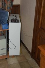
Found the cable, so here is the photo:
(I found someone mentioning a Front Fire-bdeap but there is no other info available. However the link about the various corner loading simulations I posted above, could give an idea. the list of corner-orientations to try out just gets longer and longer. 😀 )
(I found someone mentioning a Front Fire-bdeap but there is no other info available. However the link about the various corner loading simulations I posted above, could give an idea. the list of corner-orientations to try out just gets longer and longer. 😀 )
Attachments
- Status
- Not open for further replies.
- Home
- Loudspeakers
- Subwoofers
- DIY bDEAP experiences anyone