For measuring electrostatic headphone amps I would like to increase the input attenuation.
Would it be good practice to add a, say, 900k resistor in series to the single ended input? This would make a 10:1 divider with the 100k input impedance of the RTX6001. A hight input impedance is desired for electrostatic amps anyway.
For most electrostatic headphones (Stax or similar) you will need a differential measurement. 1 Meg is a significant load and you need more like 10M or even 100 M. And you need to compensate the capacitance. Fortunately the voltage swing is on the order of 200V or more so a divide by 100 probe is not an issue and the RTX has enough gain. Stray capacitance at the probe point is also an issue since the headphones are on the order of 100pF and the stray can be significant. Also use several resistors in series to reduce the voltage and associated voltage coefficients across them.
Keep in mind 200V at 20 KHz can pack quite the punch even with limited current.
My idea was to measure without headphone connected and add some capacitance in parallel so simulate the headphone. This way the stray capacitance and the input capacitance of the RTX6001 could be part of that capacitive load. Are there objection on doing so?
The capacitance of the headphones is in the order of 100 pF, equivalent to an impedance of 160 kohm at 10 kHz, so I don't think that a balanced load impedance of 2 Mohm will be a problem.
I built a KGSS amplifier some years ago. It has output resistors of 5k11 in series with each output.
I built a KGSS amplifier some years ago. It has output resistors of 5k11 in series with each output.
Shielding installation instructions?
Hello All,
Looking for help with the installation of the shielding kit for the RTX6001 that was mailed to me.
Inside the box with the analyzer I have had the unopened envelope with the shielding inside. Are the shielding installation instructions posted here anywhere?
Thanks DT
Hello All,
Looking for help with the installation of the shielding kit for the RTX6001 that was mailed to me.
Inside the box with the analyzer I have had the unopened envelope with the shielding inside. Are the shielding installation instructions posted here anywhere?
Thanks DT
Please excuse my ignorance but it's almost impossible for me to read all 305 pages at the moment.
I've been looking in getting an audio analyzer and I'd like to ask if this is a product/project that I can still purchase and if so, where can I find more information like price,where to buy, etc...
Many thanks!
I've been looking in getting an audio analyzer and I'd like to ask if this is a product/project that I can still purchase and if so, where can I find more information like price,where to buy, etc...
Many thanks!
Unfortunately the RTX6001 has been discontinued. Your best chance of getting one is probably buying one from a member of this forum.
I see. Thank you very much JensH.
BTW, is this product somehow related?
RTX6001 Audio Analyzer with Multi-Instrument Full Package | Virtins Technology
Seems still available.
BTW, is this product somehow related?
RTX6001 Audio Analyzer with Multi-Instrument Full Package | Virtins Technology
Seems still available.
Jens, am hoping you have some news soon of the mod for the power supply in the RTX6001. Is this still on your radar, or should I do something for myself (like remove the transformer into an external shielded case)?
I must admit that I haven't really worked on the power supply for a long time. On short term, moving the transformer is probably your best option, unless you have another way of supplying +/-18 V and +9 V DC.
Can we start something new collectively?
Must admit I can only contribute with money.
Shielded toroid like R&S is using?
Must admit I can only contribute with money.
Shielded toroid like R&S is using?
Last edited:
I had some transformers made with lower flux level and a metal shield around it. It helped a bit, but not very much.
Moving the transformer outside the box will give a better attenuation of the mains hum.
I have a DC/DC converter test board, which converts a +18 V input to -18 V and +9 V. It basically works, but it still needs further verification and tests.
One of the IC's reached a temperature of around 83 degrees C at full load.
I have included an eFuse on the input and ON/OFF control, which can be controlled from the USB supply or a manual ON/OFF switch.
The PCB is 50x50 mm.
Use case as heatsink?
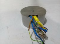
Transformer suggestion. Fully resin cast.
Transformer suggestion. Fully resin cast.
Attachments
Last edited:
Hi Jens,
I have been following this loosely. Would moving the transformer outside do most of the improvement, or should we be looking at an entirely outboard power supply?
I have one of the first units, and I am pretty happy with it. It allowed me to improve my work and understanding considerably. I can't thank you enough for all the work you put into this project and getting it to market.
-Chris
- Home
- Design & Build
- Equipment & Tools
- DIY Audio Analyzer with AK5397/AK5394A and AK4490