The ADC does of course have built-in filters. Depending on the class-D amplifier, there could still be a need for additional filtering. In principle a class-D amplifier could send out a signal, which extends from rail to rail, even though the audio signal is at a relatively low level.
I have not tested any class-D amplifiers with the RTX6001. If the class-D sends out large switching transients I think it will be necessary to use a filter in front of the analyzer.
I have not tested any class-D amplifiers with the RTX6001. If the class-D sends out large switching transients I think it will be necessary to use a filter in front of the analyzer.
One of the things i'm planning to do with this is to measure my Hypex NC400 and UcD400 amps. I think i have seen carrier residual of 450KHz on my scope at the module outputs.
Is there a way to test these modules without additional expensive filters?
Is there a way to test these modules without additional expensive filters?
It would seem to me that no matter what test equipment you were using, external filters would be required. For high power, passive L-C networks might be the way to go.
-Chris
-Chris
External filters for class D power amplifier measurement seem to be standard practice for AP and R&S test systems I have encountered.
You will either have to design or purchase an external filter if this is something you want to use this or any typical audio measurement test system to do.
When I worked for a certain large audio company decades ago we had special filter boxes for our APs and the inhouse measurement systems because they could not cope with the switching waveform still present on the output of our amps when we wanted to do performance measurements.
Invoice received
Received invoice today and wired payment. Looking forward to putting this unit to work.
Received invoice today and wired payment. Looking forward to putting this unit to work.
Hi
I plan to use audiotester V3 and REW for measuring my latest greatest amp with RTX6001 but I realize these tools do not provide a DIM30 Dynamic Intermodulation test (square wave+sine) so was wondering what you guys would advise for measuring this ?
I plan to use audiotester V3 and REW for measuring my latest greatest amp with RTX6001 but I realize these tools do not provide a DIM30 Dynamic Intermodulation test (square wave+sine) so was wondering what you guys would advise for measuring this ?
I haven't seen that test (DIM30) test used. What does it tell you in addition to the tried and true tests we already use?
-Chris
-Chris
I don't know. Is it?
ADC chips have NO analog anti-aliasing filters build in. The differential
driver opamp often has a simple R-C filter, which give about 20 dB attenuation.
When a class-D amp has rich harmonics above 3.072/2 = 1.536 MHz they will be aliased.
Sigma-Delta ADCs typcially sample at 64 x 48 kHz = 3.072 MHz and
have only digital anti-aliasing filters. Digital filters are of no use in this situaltion.
Most cheap soundcards (and analyzyers) do not bother as audio has no spectral energy above 100 kHz.
Last edited:
Thanks Joseph K
Anatech, it s all about Transient Intermodulation and Slew Induced modulation.
with google you ll find many literature from john walt or an aes paper from a team in finland. In fact, when I read the Alexander Amp paper he doesnt pay too much attention on the standard thd measurement but more on this DIM100 stuff which I d like to try.
my first understanding is that the more slew rate you have the less concern you have with TIM.
Yeah, tell us more about this intermodulation distortion stuff.
Is it a concept in search of an audience?
Is it auditable? What does it sound like?
What causes intermodulation distortion?
DT
Is it a concept in search of an audience?
Is it auditable? What does it sound like?
What causes intermodulation distortion?
DT
Any nonlinearity will enable intermodulation. Whether it's slewing or simple transfer curve you will get some nonlinearity.
However most content originates in digital (even many vinyl disks) so the content your electronics needs to handle should be within the source capability of the RTX. With its 10V output and 90 KHz power bandwidth you can stress pretty much any system past a reasonable limit.
However most content originates in digital (even many vinyl disks) so the content your electronics needs to handle should be within the source capability of the RTX. With its 10V output and 90 KHz power bandwidth you can stress pretty much any system past a reasonable limit.
walter jung document here :
http://www.waltjung.org/PDFs/SID_TIM_1.pdf
and the AES paper which you can find as a pdf with your friend google:
AES E-Library >> Method for Measuring Transient Intermodulation Distortion (TIM)
in order to be back on the topic about the Analyser, we could ask how the analyser react to TIM in other words is it doing a good job to measure TIM. we ll know soon as the first boxes are now shipping
If anyone has a digital Tim source I can process it and see what comes of loopback. I suppose I could mix an oscillator and a square wave into a low pass filter. Is that relevant in the digital age for reproducing equipment?
Hi, I ve made a 10 sec wav file with LTSpice. it is a 1MB file. here it is.
dim100_48k.wav - Google Drive
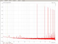
this is a 3.18khz square wave filtered 100k and modulating a 15k sine.
as per the AES paper.
but now the problem is to compare source and output and calculate %
dim100_48k.wav - Google Drive
this is a 3.18khz square wave filtered 100k and modulating a 15k sine.
as per the AES paper.
but now the problem is to compare source and output and calculate %
and here is the corresponding spectrum (audacity)
An externally hosted image should be here but it was not working when we last tested it.
- Home
- Design & Build
- Equipment & Tools
- DIY Audio Analyzer with AK5397/AK5394A and AK4490