Re: Not much of a diy'er
This should be what you are looking for I think... Check out MikeP's great recap... it was back on page 144.
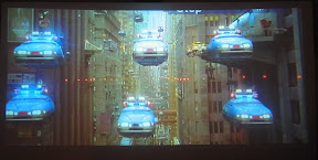
http://www.zuggsoft.com/theater/prism.htm
mustang5o said:Typically in the past I have not been much of a DIY kind of guy. Sure I change my oil, brakes and sometimes a little more then that on my cars. I have also built several computer (that is kind of my job anyway) but I have never really thought I would consider doing this type of stuff. However, I am really interested in doing a CIH setup for HT with my first projector. I have read some of this thread. Is someone putting together an instruction sheet of sorts on how to build a horizontal expansion type of anamorphic lens? I was just curious if I was going to have to read this whole thread to figure everything out or if someone was going to have step by step instructions that someone could follow? If they have been done and I just didn't find that post I apologize. If I have to read the whole thread I will start working on it now.
Thanks
This should be what you are looking for I think... Check out MikeP's great recap... it was back on page 144.
http://www.zuggsoft.com/theater/prism.htm
how to make the right curve has been posted here I'm sure, also on avs forums...
easiest way is with the projecto the correct distance you want from the screen with projection in animorph ( with lense stretch on - this will give an image with top and bottom curved - the amount depending on distance to flat surface and what projector you have), get a long stick that will be vertically level and long enough to reach the ground and the top of your image, against the flat surface measure top and bottom points in the center of your image ( shortest vertical points), then go to one side of your image (L or R - or try both), and with the stick still vertical bring the stick out towards the projector until the image can be seen on the stick the same height as the marked points you did in the center. then with the stick perfectly vertically level, measure the distance to the wall ( taking into account the depth of the stick). This is your "rise" height, or the distance you need to bring the edges of the screen out compared to the center to make the image square.
I have just set my lense back up, but need to do a little bit more adjusting to get the image square, but you can see it does look straighter than my previous images on flat surface. ( last 7 images)
I basically put the lenses back up and fitted it in the screen - not neccessaraly the correct aspect yet, need to measure & set lenses and zoom correctly, then I can take measurements for building the masking.
just measured the image with photo editor and aspect is 2.22, so I need to zoom out a little bit and widen the lenses a touch to get corect 2.35:1
from this photo foward is snapshot of curved screen in action...

This is the last shot in the series...
easiest way is with the projecto the correct distance you want from the screen with projection in animorph ( with lense stretch on - this will give an image with top and bottom curved - the amount depending on distance to flat surface and what projector you have), get a long stick that will be vertically level and long enough to reach the ground and the top of your image, against the flat surface measure top and bottom points in the center of your image ( shortest vertical points), then go to one side of your image (L or R - or try both), and with the stick still vertical bring the stick out towards the projector until the image can be seen on the stick the same height as the marked points you did in the center. then with the stick perfectly vertically level, measure the distance to the wall ( taking into account the depth of the stick). This is your "rise" height, or the distance you need to bring the edges of the screen out compared to the center to make the image square.
I have just set my lense back up, but need to do a little bit more adjusting to get the image square, but you can see it does look straighter than my previous images on flat surface. ( last 7 images)
I basically put the lenses back up and fitted it in the screen - not neccessaraly the correct aspect yet, need to measure & set lenses and zoom correctly, then I can take measurements for building the masking.
just measured the image with photo editor and aspect is 2.22, so I need to zoom out a little bit and widen the lenses a touch to get corect 2.35:1
from this photo foward is snapshot of curved screen in action...
This is the last shot in the series...
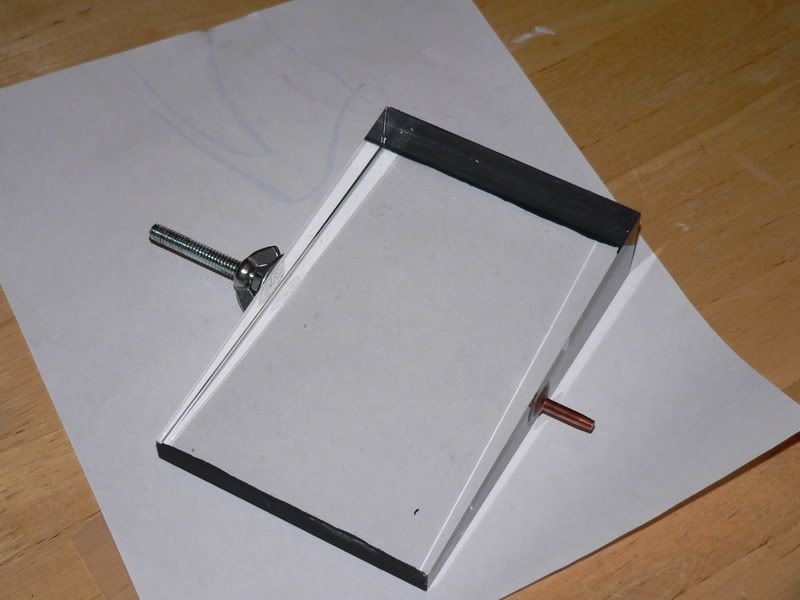
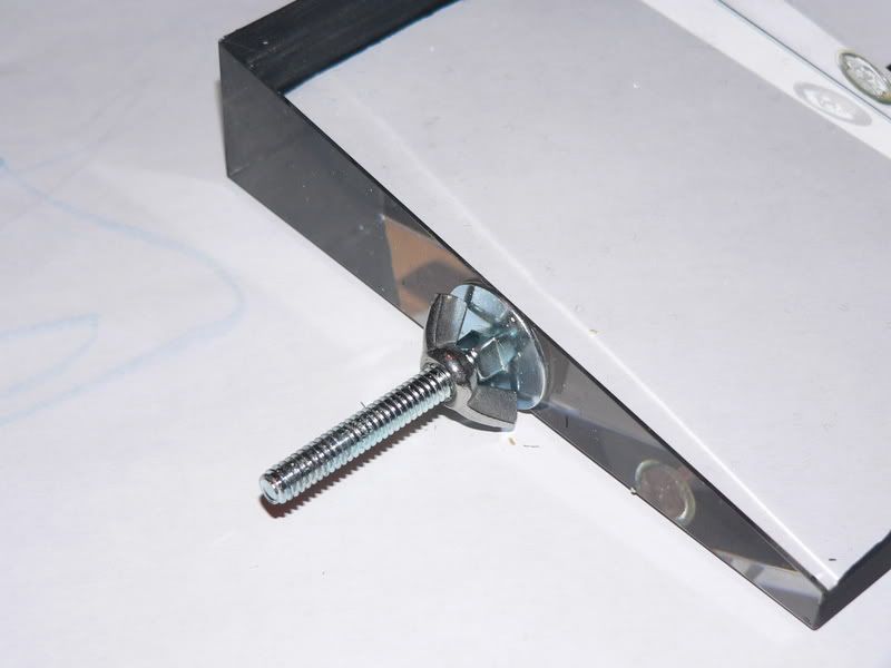
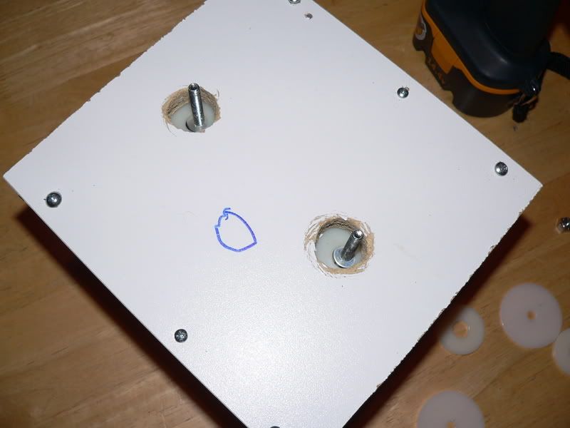
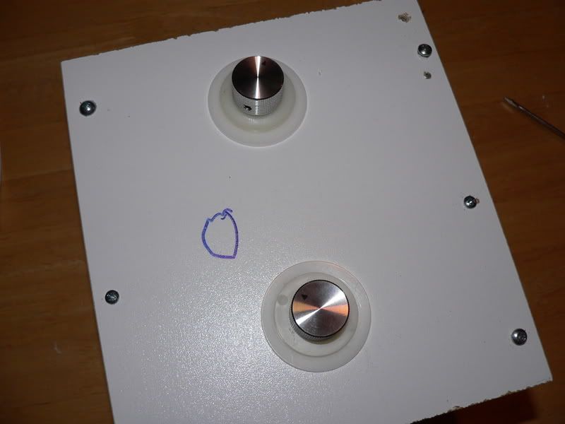
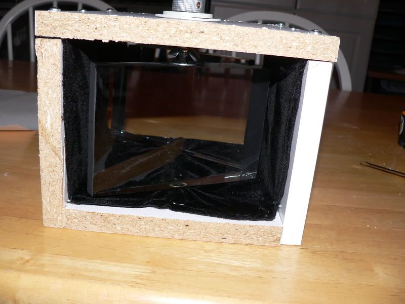
I promised some photographs last week relating to my housing, and my "infinitely adjustable lens." (Each prism has the ability to spin or adjust front/back and left/right. As I said before, the housing itself is not all that pretty--I will be re-doing it once I get everything down the way I want. (In other words, the housing is quite ugly--and even includes some freehand art (blue marker) from my son--it's much worse on the other side!) But this gives an idea of how the adjustments are made.
The first two images show a prism with a bolt adhered on top, and a rivet on the bottom:
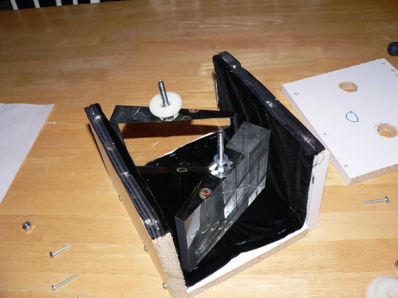
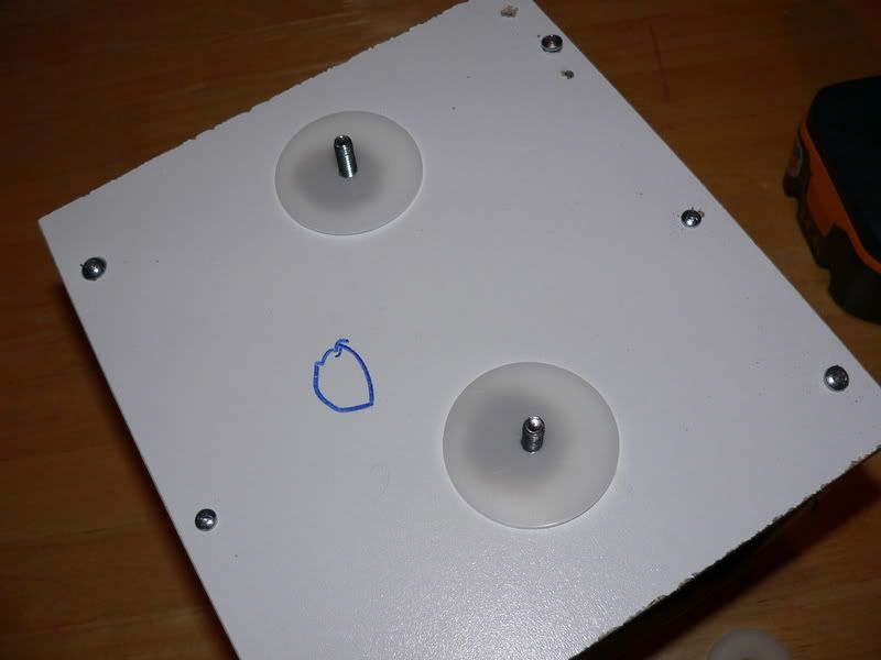
The next show the housing without the top, but with the prisms inside, with the rivets adhered to the bottoms of the prisms sitting in their "wells":
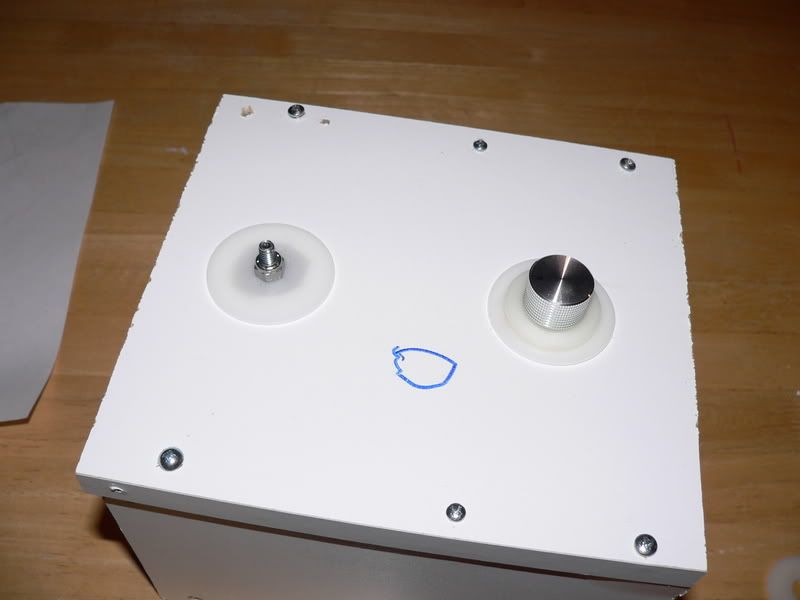
The next series shows the top of the housing, and the various pieces used to bring it all together:
This one shows the lens with the adjustment knobs in "pass through mode":
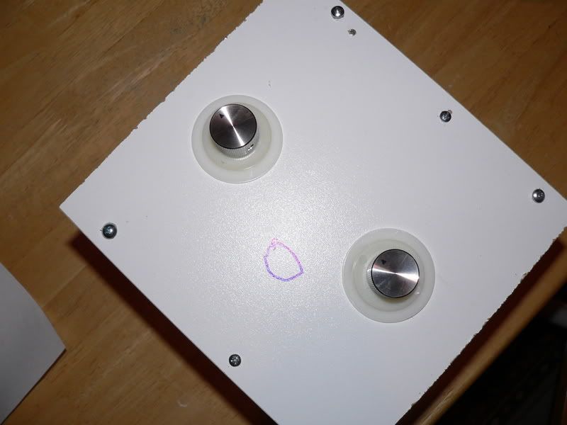
The next shows the lens with the adjustment knobs in "stretch" mode. In reality, I will be able to have two "stretch" modes--one for 16:9 and one for 21:9:
Other things I have done: I have painted the ends of the prisms with a flat black paint mixed with corn starch to minimize reflections. I have also lined the inside of the housing with black velvet. This makes the interior quite dark, and I believe does a good job of minimizing reflections:
The first two images show a prism with a bolt adhered on top, and a rivet on the bottom:
The next show the housing without the top, but with the prisms inside, with the rivets adhered to the bottoms of the prisms sitting in their "wells":
The next series shows the top of the housing, and the various pieces used to bring it all together:
This one shows the lens with the adjustment knobs in "pass through mode":
The next shows the lens with the adjustment knobs in "stretch" mode. In reality, I will be able to have two "stretch" modes--one for 16:9 and one for 21:9:
Other things I have done: I have painted the ends of the prisms with a flat black paint mixed with corn starch to minimize reflections. I have also lined the inside of the housing with black velvet. This makes the interior quite dark, and I believe does a good job of minimizing reflections:
Steve,
The case needs some re-finements, but I think from a design persective, your on a winner. Well done 🙂
Mark
The case needs some re-finements, but I think from a design persective, your on a winner. Well done 🙂
Mark
Yeah--it's not pretty, is it? I have chopped those boards up so much, it's not funny. But it is more for proof of concept, and once I get the final design, I'll work on making it look nice.
Mark Techer said:So the holes in the top, are they about 25mm - 32mm (1" - 1.25")?
Mark
I used the largest wood borer I had in my toolset, and I think it is 1.25". (It could be 1.5", not quite sure right now)--anyway, they are large enough to move the bolts and, hence, the prisms, sufficiently in any direction before tightening down.
One thing I am nervous about--should the adhesive fail on the bolt or the rivet, the prism will likely just fall right out of the housing (some here can attest to the danger of falling prisms!)
What should I do to better anchor these things into place? Some have suggested plexiglass or lexan cut in the shape of the wedge, with an indentation around the bolt head, and adhering that to the surfaces as well. Any other suggestions?
Steve Scherrer said:Any other suggestions?
How about a combination of rubber (mouse pad might do) and your attachment system. My prisms are "sandwitched" in using two peices of foam. I can then turn the lens 90degrees to make a VC with nothing moving.
Your idea is simple and effective, so I just drew one up to see if it would work with my prisms. It looks like I would need to widen the case...
Mark
Steve, interesting stuff. Have you been able to get the prism to stay at the intended angle? I have been unable to get rid of my 2" or so vertical offset with my first attempt at an enclosure. Some experimentation yields that I need to tilt both prisms back towards the PJ quite a bit, with the enclosure I built I can't easily tilt them enough and still rotate them correctly. Either something is screwy with the enclosure I made (entirely possible as I wasn't too careful with being exact on much of it) or I need something like what you've done. Anyu chance of a shot of what the "wells" look like?
Also if I have this correct, you've got a wing nut + plastic washer + metal washer on the inside of the top, plus 2 plastic washers + nut on the outside? The knob just fits over the nut? Where did you find the knobs?
I'd have to widen my enclosure also. The notion of the "pass through" is interesting, I had assembled a sliding rail to move the lens out of the way, but I'm not sure that it's sturdy or well designed enough.
So far I have had no problem with getting the prisms to stay where I need them to. Once tightened, the plastic washers provide enough friction to keep the prisms from freely rotating, but allows them to when I twist the knob.
I have not had a chance to ceiling mount it yet, but have only been able to test this out table mounted. I am hoping to rely on a combination of tilt from the housing itself (attached to the brackets, that I have yet to add to my housing) and fine-tune by adjusting each prisms within the housing through the holes in the top of the housing.
The wells are simple--really just holes drilled into the bottom of the housing that I then popped a plastic casing into. There is nothing special about the wells except they allow the prism to freely move within them.
I found the knobs at radioshack. On the inside, I have the upside down wing nut (just to provide a surface for the metal washer, followed by the plastic washer. In reality, I added the metal washer to add a little more surface area between the wing nut and the plastic washer, and because the hole of the washer was a little bigger than I wanted it to be. I could probably get by with just a thicker plastic washer with the hole the same size as the bolt.
Thanks guys
I will take the time to go back a bit (page 144 or maybe page 62) and get caught up on more info. If I am going to do a DIY lens I want to be able to get started on it fairly soon so I can work out the tweaks and setup before I figure out my screen (which I also plan to build if things go well). Then again, I might need a drop down AT screen for my setup so, we'll see how that goes. Seeing proof of concept makes me feel more secure about doing this myself.
Thanks again.
Whew! Finally finished this thread today!
Fantastic work guys! I am considering building one myself - I can really see the difference when you show the film at its correct size!
I have been scouring the Internet for more materials and I found a 9" x 5" wedge if anyone needs a larger prism. Here's the address:
www.promopeddler.com/Detail/62984/202-9
I'm still looking for a larger degree angle and will post that when I find one.
Thanks for making this thread!
Do you guys think clear Lucite would work?
Look at the Wedge Prism on this page:
www.abetteridea.com/stshapes1page.htm
Look at the Wedge Prism on this page:
www.abetteridea.com/stshapes1page.htm
I also noticed on the website for Lambda Research Optics that they arrange their anamorphic prism pairs differently than what has been shown in this thread. Take a look at this page where the prism arrangement and the light path are shown in a drawing:
www.lambda.cc/PAGE131.htm
Is this different than what you are attempting to do here?
www.lambda.cc/PAGE131.htm
Is this different than what you are attempting to do here?
solarscreen said:Do you guys think clear Lucite would work?
Look at the Wedge Prism on this page:
www.abetteridea.com/stshapes1page.htm
I do think Lucite would work. Any idea how much that prism cost? It looks like it has a much greater angle, and could replicate the doubling of prisms that some here have done to reduce CA.
not sure about lucite, but they look clear, but their optical accuracy might not be enough for projection... ie might get too much colour seperation or loss of a particular colour through the material.
If they are cheap enough and you can't get the crystal wedges, then give it a shot.
the Lamda research prism pair looks pretty good, but the angle looks quite large, that configuration they are showing is exaclty how mine are setup with both 90deg corners facing the projector.
and yea it's a bit of a wade through this thread, but your best bet is to open word pad, and go through every page, and copy bits out you think you will ned, thats what I did 🙂 helped to condense the information I required to get mine setup.
for beginers I'd recommend to just get the wedges first, and then put the projector on a flat surface and fiddle around with the angles till you get it right, it's quite easy.
get largest ones you can afford or think will do ( or use the white a4 sheet method to work out how big a lense you will need) , just remember if your projector is close to the screen then you might have troubles.
based on what If done and seen about anamorphic ratio's you can get an idea if it will work with your projector is to calculate the ratio by:
ratio = distance to projector/16:9 unexpanded image width
if the ratio is greater than 1.5 then you shouldn't have a problem.
my ratio is 1.47 and the image just fits in the second prism (170mmx150mm)
I could do with moving the projector back another 1000mm to get a near perfect 2.0 ratio which will give me more play with the projected screen size.
I have a problem at the moment with the vga over cat5 as I have extended the length with a vga extender & is causing some bleed through of RGB through the range, so I will be re-doing my pc - projector with changing it to DVI to HDMI cable next week.
Stevo,
When I get pricing, I'll see if I can't pick up a couple.
My projector has a TR of 1.5 to 1.8 so I'm good there.
Thanks for the tips and advice!
John
When I get pricing, I'll see if I can't pick up a couple.
My projector has a TR of 1.5 to 1.8 so I'm good there.
Thanks for the tips and advice!
John
solarscreen said:I also noticed on the website for Lambda Research Optics that they arrange their anamorphic prism pairs differently than what has been shown in this thread. Take a look at this page where the prism arrangement and the light path are shown in a drawing:
www.lambda.cc/PAGE131.htm
Is this different than what you are attempting to do here?
That is interesting. If we tried those angles at home, we would most likely end up with Horizontal Compression. Note the incoming beam shoots into the steeply angled prism which is almost the same as our front or exit prism. I am a little dubious about their exit prism, though go back to page 39(?) and check out how my original water prisms were set...
Steve Scherrer said:
I do think Lucite would work. Any idea how much that prism cost? It looks like it has a much greater angle, and could replicate the doubling of prisms that some here have done to reduce CA.
So is this material some composite plastic? I agree with Steve, it should work if the faces are flat. The steeper angle means that prisms displacement will not need to be as severe, and that alone wil help reduce CA. There will still be CA, as your still only using a pair of prisms and that pair are made from the same material...
Now combine one of these with an optic glass prisms, and you might have something new 🙂
Mark
Maybe I'm looking at the picture wrong at Lambda - I was assuming, since I read left to right, that the projector would shine into the prisms at D1 and would exit as HE at D2.
- Home
- General Interest
- Everything Else
- The Moving Image
- Optics
- DIY anamorphic lens