Nice if you can get one, and why we are here discussing prisms on a DIY site.
I would like to see some chat about cylidrical elements if anyone has had any experiences with them...
Mark
I would like to see some chat about cylidrical elements if anyone has had any experiences with them...
Mark
Collimating Elements
I'm all ready to talk about cylindrical elements, but before we get too far down that road, I have a question.
ONE of our challenges with a DIY lens is that the prism designs that are in use commonly sit well away from the primary optic on the projector. This means that the glass has to be large to accommodate the (relatively) short throws for most home projectors. This large glass puts us well into custom land when it comes to optic glass which is way too expensive for a DIY project. As a result we're limited to using cheaper alternatives such as trophies and such and finding optically coated alternatives is difficult.
In addition to all the reading I've been doing about anamorphic lenses, I've been doing a load of looking around, and finding optical elements anywhere over 100mm is really difficult. Finding elements below 50mm is exceptionally easy. In between its a mixed picture, but workable (I think.) The only widely available source for large-ish optics is eyeglass lens blanks. These are available in 100mm disks at a variety of optical powers and coatings.
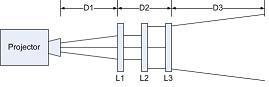
Which brings me to my ?. Have a look at the attached image. It is a purely notional top down look at a projector and a set of lenses. Nothing is to scale. In the drawing, I'm showing a projector, and a set of lens groups (L1, L2, and L3).
As the drawing shows, light leaving the projector is dispersing on its way to a screen. We can see that the farther away the lens is from the projector (D1), the larger our optics needs to be to accommodate the widening beam. Conversely, As D1 approaches zero, the width of the beam narrows. Additionally, unless we do something about that widening beam, the width of the final lens element must accommodate the width of the beam at the exit point (D1 + D2), so complex manipulation, or manipulation that takes much distance is out of the question because the exit optics must be huge to accommodate.
On example is that in the current prism based approach, the exit optic must be large because the design necessitates that the final prism is far from the projector exit lens (i.e. Large D1+D2).
I propose (I know this isn't novel, but I want to get us talking about this in an engineering dialog), that we look seriously at the addition of leading and trailing optics in a lens (L1 and L3) that are of complimentary powers that act to collimate the light and allow us to manipulate it with our primary lens group (L2).
Again, I'm ignoring for a moment the costs of the optics. I also understand that a single element pair won't work for ALL throw ratios, but since this is DIY, we should be able to identify multiple pairs of leading and trailing optics that accommodate varying throw ratios. This approach is taken for commercial projection lenses, we should consider doing the same.
The benefit of solving this part of the problem, is that if we design the leading element (L1) appropriately, we should be able to put it right up next to the output of the projector while the image beam is still small. Additionally, since the light beam will be essentially collimated, we can have a long lens to accommodate whatever manipulation we might need to get the anamorphic stretch we want in L2.
It seems to me this is the answer to being able to find easily source-able optics. Am I totally off base here?
riskpeep
I'm all ready to talk about cylindrical elements, but before we get too far down that road, I have a question.
ONE of our challenges with a DIY lens is that the prism designs that are in use commonly sit well away from the primary optic on the projector. This means that the glass has to be large to accommodate the (relatively) short throws for most home projectors. This large glass puts us well into custom land when it comes to optic glass which is way too expensive for a DIY project. As a result we're limited to using cheaper alternatives such as trophies and such and finding optically coated alternatives is difficult.
In addition to all the reading I've been doing about anamorphic lenses, I've been doing a load of looking around, and finding optical elements anywhere over 100mm is really difficult. Finding elements below 50mm is exceptionally easy. In between its a mixed picture, but workable (I think.) The only widely available source for large-ish optics is eyeglass lens blanks. These are available in 100mm disks at a variety of optical powers and coatings.
Which brings me to my ?. Have a look at the attached image. It is a purely notional top down look at a projector and a set of lenses. Nothing is to scale. In the drawing, I'm showing a projector, and a set of lens groups (L1, L2, and L3).
As the drawing shows, light leaving the projector is dispersing on its way to a screen. We can see that the farther away the lens is from the projector (D1), the larger our optics needs to be to accommodate the widening beam. Conversely, As D1 approaches zero, the width of the beam narrows. Additionally, unless we do something about that widening beam, the width of the final lens element must accommodate the width of the beam at the exit point (D1 + D2), so complex manipulation, or manipulation that takes much distance is out of the question because the exit optics must be huge to accommodate.
On example is that in the current prism based approach, the exit optic must be large because the design necessitates that the final prism is far from the projector exit lens (i.e. Large D1+D2).
I propose (I know this isn't novel, but I want to get us talking about this in an engineering dialog), that we look seriously at the addition of leading and trailing optics in a lens (L1 and L3) that are of complimentary powers that act to collimate the light and allow us to manipulate it with our primary lens group (L2).
Again, I'm ignoring for a moment the costs of the optics. I also understand that a single element pair won't work for ALL throw ratios, but since this is DIY, we should be able to identify multiple pairs of leading and trailing optics that accommodate varying throw ratios. This approach is taken for commercial projection lenses, we should consider doing the same.
The benefit of solving this part of the problem, is that if we design the leading element (L1) appropriately, we should be able to put it right up next to the output of the projector while the image beam is still small. Additionally, since the light beam will be essentially collimated, we can have a long lens to accommodate whatever manipulation we might need to get the anamorphic stretch we want in L2.
It seems to me this is the answer to being able to find easily source-able optics. Am I totally off base here?
riskpeep
Attachments
Riskpeep,
what an awesome post! I would very much like to discuss this in the fashion you suggest if I can keep up 😉
Looking at your drawing, why is D1 that far?
I have my prisms based Anamorphic Lens with D1 so that the case is just off the front of the projector so that when I move the anamorphic lens, there is no contact.
I have set one up (becuase the owner does not move the lens ever) where the primary lens of the projector is actually just inside the case very close the rear prism.
Your right about finding large size cylindrical elements though. The one I have (plano-convex) is just 40mm x 30mm, so way too small to work with my projector, even if I was to extend the TR. At my current TR, I would need at least 125mm tall elements.
I am looking forward to this as an on going topic...
Cheers,
Mark
Collimating Elements
Mark,
The drawing is completely out of scale and really only to foster discussion and highlight the variables we're talking about.
So in answer to your question, D1 isn't really that far at all, its just that I wanted to show that there is a distance there that is non-zero.
WRT your prism lenses, its good to hear that you're putting your lenses right up against the projector lens, as that confirms one part of the theory. But as I'm sure you know, the challenge with prism lenses is that the distance from the front to the back is relatively large (compared to an ISCO for example), and as a result you need big prisms for short throws.
My thinking about front and back elements got started for me when I saw the attached picture from the Widescreen museum (http://www.widescreenmuseum.com/Widescreen/wingvv2.htm) showing an early prism based design. Even in this early design they were using leading and trailing elements.
As far as being able to keep it up... Well... I don't know jack about optics, but I am an engineer so my tendency is towards structure and verbosity. Plus, my understanding about where we'll need to go to make a functional lens based on a cylindrical design is that we'll need to be a bit more on purpose as we go forward because they approach isn't as flexible as the prism based approach.
With all that being said, for you to be as interested as you sound, I'm humbled to think I must be getting something right. Your name is all over the forums, and I think you've really contributed an incredible amount over the years.
riskpeep
Attachments
Re: Collimating Elements
Correct, there is always going to be an air gap of a certain amount between the primary projector lens and the anamorphic lens. This is also the case fro commercial cinema too...
ISCO III is not a small lens at almost 6" [150mm] diameter and about 5" [125mm] deep.
Granted, the prism anamorphic adaptors we've discussed and made here are around (and in some cases larger) 8" [200mm] deep. Mine is. My throw ratio is also under 1.3:1, so very short, so the prisms have to be large also to prevent vignetting...
And it makes sense too. If I am understanding the diagram correctly, they have used an achromatic doublet (Miniscus lens made from bonding a bi convex to a bi concave - each part made from different glass to correct for CA as well), then two prisms, then a final (focal?) element...
Well thank you. I am learning new stuff everyday and I just find this topic so interesting that I almost feel compelled to help others understand as well...
Mark
riskpeep said:The drawing is completely out of scale and really only to foster discussion and highlight the variables we're talking about.
So in answer to your question, D1 isn't really that far at all, its just that I wanted to show that there is a distance there that is non-zero.[/i]
Correct, there is always going to be an air gap of a certain amount between the primary projector lens and the anamorphic lens. This is also the case fro commercial cinema too...
WRT your prism lenses, its good to hear that you're putting your lenses right up against the projector lens, as that confirms one part of the theory. But as I'm sure you know, the challenge with prism lenses is that the distance from the front to the back is relatively large (compared to an ISCO for example), and as a result you need big prisms for short throws.
ISCO III is not a small lens at almost 6" [150mm] diameter and about 5" [125mm] deep.
Granted, the prism anamorphic adaptors we've discussed and made here are around (and in some cases larger) 8" [200mm] deep. Mine is. My throw ratio is also under 1.3:1, so very short, so the prisms have to be large also to prevent vignetting...
My thinking about front and back elements got started for me when I saw the attached picture from the Widescreen museum (http://www.widescreenmuseum.com/Widescreen/wingvv2.htm) showing an early prism based design. Even in this early design they were using leading and trailing elements.
And it makes sense too. If I am understanding the diagram correctly, they have used an achromatic doublet (Miniscus lens made from bonding a bi convex to a bi concave - each part made from different glass to correct for CA as well), then two prisms, then a final (focal?) element...
As far as being able to keep it up... Well... I don't know jack about optics, but I am an engineer so my tendency is towards structure and verbosity. Plus, my understanding about where we'll need to go to make a functional lens based on a cylindrical design is that we'll need to be a bit more on purpose as we go forward because they approach isn't as flexible as the prism based approach.
With all that being said, for you to be as interested as you sound, I'm humbled to think I must be getting something right. Your name is all over the forums, and I think you've really contributed an incredible amount over the years.
riskpeep
Well thank you. I am learning new stuff everyday and I just find this topic so interesting that I almost feel compelled to help others understand as well...
Mark
So we want D1 to be near zero. If we assume that we can approach zero with D1, and lens group L1 can collimate the light, then the input to our lens at L1 should be very nearly equal to the size as it comes out of the projector.
If we assume a 1.33x horizontal expansion, then the maximum width of the light path moving through the lens is the input width times 1.33. To accommodate that width, then, assuming a round lens, we'd need a lens slightly larger to accommodate the diagonal. (Think about a rectangle inscribed inside of a circle and you get the idea here.) The other thing to consider is that for lenses I'm fairly certian that the usable area of the lens is some percentage smaller than the actual diameter. The exact diameter would be related to the diagonal of the image, perhaps something like this:
min diameter = 1.05 * SQRT( (1.33xWidth)^2 + Height^2)
This assumes a 5% safety margin on the edge of the lens.
For my projector (PT-AE1000U) at my throw ratio (~1.5 for a 16:9 sceen), the exit image size is a little under 1.5" (38.1 mm) wide. I don't know if this is typical or not.
If I run this calculation for my situation, then I get this:
min diameter = 1.05 * SQRT((1.33x38.1)^2 + 21.431^2)
min diameter = 57.76mm
So theoretically, for my setup I could get away with optics that were just 60 mm wide at the exit group. Entry optics could be even smaller, around 46 mm or so.
Does this sound right? Again, all this assumes we can use an FE and BE element to collimate and de-collimate the light so the only expansion going on in the lens is what we do to get the animorphic expansion we want.
On a related note, if we were to make a VC lens, the optics get even more friendly as we're shrinking the image, not expanding it. On second thought perhaps not, because that would be a CIW image. To get the image I want I'd have to zoom it back out and I think the math would end up the same on the exit side of the lens.
Riskpeep
riskpeep said:So we want D1 to be near zero. If we assume that we can approach zero with D1, and lens group L1 can collimate the light, then the input to our lens at L1 should be very nearly equal to the size as it comes out of the projector.
Yes it will be close, so TR pending, the rear element can be much smaller than the front...
Also don't forget the rate at which the light path expands as it moves away from the primary lens. It is also better to use the centre portion of the lens rather then push the limits of the entire surface...riskpeep said:If we assume a 1.33x horizontal expansion, then the maximum width of the light path moving through the lens is the input width times 1.33. To accommodate that width, then, assuming a round lens, we'd need a lens slightly larger to accommodate the diagonal. (Think about a rectangle inscribed inside of a circle and you get the idea here.) The other thing to consider is that for lenses I'm fairly certian that the usable area of the lens is some percentage smaller than the actual diameter. The exact diameter would be related to the diagonal of the image, perhaps something like this:
min diameter = 1.05 * SQRT( (1.33xWidth)^2 + Height^2)
This assumes a 5% safety margin on the edge of the lens.
riskpeep said:For my projector (PT-AE1000U) at my throw ratio (~1.5 for a 16:9 sceen), the exit image size is a little under 1.5" (38.1 mm) wide. I don't know if this is typical or not.
If I run this calculation for my situation, then I get this:
min diameter = 1.05 * SQRT((1.33x38.1)^2 + 21.431^2)
min diameter = 57.76mm
So theoretically, for my setup I could get away with optics that were just 60 mm wide at the exit group. Entry optics could be even smaller, around 46 mm or so.
Does this sound right? Again, all this assumes we can use an FE and BE element to collimate and de-collimate the light so the only expansion going on in the lens is what we do to get the animorphic expansion we want.
It does, but the problem is that 40 x 60mm element I have is 40mm wide and 60mm high when orientated to work as a HE lens...
riskpeep said:On a related note, if we were to make a VC lens, the optics get even more friendly as we're shrinking the image, not expanding it. On second thought perhaps not, because that would be a CIW image. To get the image I want I'd have to zoom it back out and I think the math would end up the same on the exit side of the lens.
Riskpeep
Yes and this element might actually work if turned around, but personnally, I still think it is too small. Its only real use might be a vertical expansion lens which is not useful for HT...
Mark
Lens Modelling SW
As I play around with these lenses more, it would be really helpful to have a good lens modelling program.
Does anyone know of one that is free or really cheap that would let us design lenses?
Ideally it would be flexible enough to let us experiment with both cylindrical lens based and prism based solutions. Bonus would be an ability to model CA so we could design it out.
Riskpeep
The only one I have ever seen is a free version from the French guys, but is was only to do with prisms...
Mark
Mark
Re: Lens Modelling SW
I have played with OSLO EDU. It can be found at http://www.lambdares.com/education/oslo_edu/ To quote their site:
From playing around with it, it should be useful for the DIY community and the ATM (Amateur Telescope Maker) communities. Be warned, download the manual and be prepared to spend some time learning to use this powerful tool.
(The links at http://www.sinopt.com no longer work. I guess there was some sort of change of ownership or at least site.)
riskpeep said:As I play around with these lenses more, it would be really helpful to have a good lens modelling program.
Does anyone know of one that is free or really cheap that would let us design lenses?
Ideally it would be flexible enough to let us experiment with both cylindrical lens based and prism based solutions. Bonus would be an ability to model CA so we could design it out.
Riskpeep
I have played with OSLO EDU. It can be found at http://www.lambdares.com/education/oslo_edu/ To quote their site:
OSLO-EDU is a free Windows program with a reduced number of features compared to OSLO Light. It also restricts you to working with systems that have up to, or including, 10 surfaces. Although OSLO-EDU does not include all the capabilities of OSLO Light, Standard or Premium, it does give you optical design power that exceeds many commercial programs. OSLO-EDU gives you the basic ability to lay out, edit, optimize, analyze, tolerance, and save a wide range of optical systems. OSLO-EDU is perfectly tailored for educational use.
From playing around with it, it should be useful for the DIY community and the ATM (Amateur Telescope Maker) communities. Be warned, download the manual and be prepared to spend some time learning to use this powerful tool.
(The links at http://www.sinopt.com no longer work. I guess there was some sort of change of ownership or at least site.)
OSLO examples
I posted some OSLO examples of an ideal projector lens with lens shift for a HE and VC 5 degree prism pairs at my web site at http://computertips.toups.info/optics/ This roughly mirrors my setup parameters.
More explanations later, hopefully in a few days.
I posted some OSLO examples of an ideal projector lens with lens shift for a HE and VC 5 degree prism pairs at my web site at http://computertips.toups.info/optics/ This roughly mirrors my setup parameters.
More explanations later, hopefully in a few days.
off-topic - prism sources in UK / EU
Hi all,
Just a quick question - I'm looking to build myself an anamorphic lens for my PJ (currently an Infocus SP4805, but about to pull the trigger on a Panasonic AX200). However, Googling for several hours reveals only one source of optical crystal wedges in the UK, and they have a minimum order quantity of circa 18 wedges!!! 🙁
I've emailed Massillon Plaque, and received the rather abrupt reply
"We don't ship overseas"
(no signature, no "Dear Neil", etc, etc - not what I've come to expect from my cousins across the pond, frankly!) 😡
Does anyone know of a supplier in the UK for the crystal wedges?
Thanks.
Neil.
Here's one >>> http://www.bruneltrophies.co.uk/shop/corporate_awards/crystalawards/jb1061/
Personally I am looking at making my one out of AR glass.
This is my first post so sorry if I have broken any rules.
Personally I am looking at making my one out of AR glass.
This is my first post so sorry if I have broken any rules.
iseealiens said:Here's one >>> http://www.bruneltrophies.co.uk/shop/corporate_awards/crystalawards/jb1061/
Personally I am looking at making my one out of AR glass.
This is my first post so sorry if I have broken any rules.
Your right 🙂 Those prisms look like the same ones from MP that have been used by many on these forums already. Where did you look to get AR coating?
Mark
iseealiens said:Here's one >>> http://www.bruneltrophies.co.uk/shop/corporate_awards/crystalawards/jb1061/
Personally I am looking at making my one out of AR glass.
This is my first post so sorry if I have broken any rules.
issaliens - thanks for this! Looks like Google isn't as much my friend as I thought! 😉
Mark,
Email sent, but if those are the same wedges as MP, then I think I am set!
Mark Techer said:
Your right 🙂 Those prisms look like the same ones from MP that have been used by many on these forums already. Where did you look to get AR coating?
Mark
I think iseealiens is talking about making liquid-filled prisms from AR glass - correct?
Thanks again to you both!

Neil.
Sorry Mark I should have been clearer; nelliekins is correct I am planning on making mines’ liquid filled for the reason that I think it would be to hard to find someone that will do AR coating on these trophy wedges in the UK.
JB1061 is the 6” plaque number and if you Google it will show other company’s in the UK that sell them. JB1062 is the 7” and JB1063 is the 7.5”.
Let me know if anyone finds a company that can do AR coating in the UK for a reasonable price.
I have one question? Is it better to use these trophy wedges rather then constructing ones liquid filled? And why?
Cheers
- Home
- General Interest
- Everything Else
- The Moving Image
- Optics
- DIY anamorphic lens