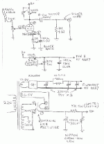
HI, Need advice on this circuit.
I built this pre-amp according to the attached circuit.
However I did not follow completely on the rectifier tube, I am using a 6CA4, a hammond 369jX transformer which can suply 250V-0-250V iso of the suggested 200V-0-200V trafo.
I am using DC6.3V fil supply iso 12.6V as suggested.
Apart from this, I also put a 4.7uF cap iso suggested 0.1uF.
The problem I face now is that whenever I adjust the volume control, I can see DC drift at the output as such it will make my power amp goes into protection.
I am wondering if it is releated to the big ouptut cap that I used or the higher B+ supply that I have ?
Please help !!!
Finally, in this circuit, there is this B+ supply that is being divided between 20K and 100K and it is being connected to pin 8 of the 5687. Can someone advice the purpose of this arrangement ? In my case as I am using 6.3V DC, is it still necessary to make the connection to Pin 8 ??
Many thanks in advance
Mark
Attachments
Details of project using the same schematic here: http://diyparadise.com/simplepreamp.html
Other 5687 projects here:
http://diyaudioprojects.com/Tubes/5687/
http://www.dhtrob.com/schemas/afbeeldingen/5687pre.gif
Datasheet of 5687: http://www.pmillett.com/tubedata/HB-3/Receiving-Type_Industrial_Tubes/5687.PDF
If you have the output capacitor in place then there should be no DC on the output at all. Make sure the capacitor has the correct DC voltage rating. Check to see that you have taken the output from the correct side of the capacitor.
Only use 6.3 V heaters if the heaters of each tube are in parallel, and use 12.6 V if you run the heaters of each tube in series.
Pin 8 is to the centre of heaters. In your project pin 8 is used to add a DC voltage ‘offset’ to the heaters. However the datasheet of the 5687 states that the tube is safe with up to 100V difference between heater and cathode, so I am not sure that it needs the DC voltage ‘offset’.
Hi Gordy thanks for your answer.
I found my problem...... my mistake in wrongly wired pin 2 (gate) and pin 3 (cathode) . After corrected the wiring (luckily the tube still ok.... ), the pre-amp is up and running !!! 🙂
Also on the Pin 8 thingy... I remove the connection to the B+... and added a 100Ohm series to Pin 2 (without this when I turn the volume to minimum... the amp seems to become unstable....)
The pre-amp is very very quiet....Just remember not to ground the heater supply near to the tube...i.e return the ground back to the supply capacitor and then ground it with the B+ supply capacitor ground...
By the way I did a quick measurement on the frequency response is about 80Khz at 3dB point..... I thought for valve it can be easily >100Khz....
Anyway it is working now .......
Many Thanks.
Mark
It is my clone Audio Note M7
An externally hosted image should be here but it was not working when we last tested it.
- Status
- Not open for further replies.
