aha so you laminated paper with the new tape then onto the cutting mat, cut everything then apply spray glueto the PVDC >? looking good btw!
or did you sray glue the paper onto the alu tape, then cut. and removed backing and stuck it to the PVDC with the acrylic that is on the aluminum tape ?
or did you sray glue the paper onto the alu tape, then cut. and removed backing and stuck it to the PVDC with the acrylic that is on the aluminum tape ?
Last edited:
Forget about laminated paper yet.
I took my cutting mat , placed my new alu tape ,alu down, cut with the silhouette, removed leftovers, removed the lining, (non stick paper) ,took the PVDC on a acrylic plate with a little water on.Placed the plate with the PVDC on top of the cutting mat.
Just folded and glued the ends with non acid silicone ,
 [/url][/IMG]
Drawing was not perfect, but I can make a test later. Needs one more" turn ".
Bernt
I took my cutting mat , placed my new alu tape ,alu down, cut with the silhouette, removed leftovers, removed the lining, (non stick paper) ,took the PVDC on a acrylic plate with a little water on.Placed the plate with the PVDC on top of the cutting mat.
Just folded and glued the ends with non acid silicone ,
Drawing was not perfect, but I can make a test later. Needs one more" turn ".
Bernt
Last edited:
It is quite easy to work it.
I made my own alu/paper with 10my household alu and copy paper.
Bernt
Yeah, I'll try that as well.
Just to clarify, the aluminium on a paper liner is necessary when the Silhouette cutter is used. Bare aluminium gets ripped otherwise.
this is the latest measurement:
 [/url][/IMG]
looking good.
Res. freq. 149Hz.
This is a very fragile diaphragm!!!!!!!!
Bernt
looking good.
Res. freq. 149Hz.
This is a very fragile diaphragm!!!!!!!!
Bernt
this is the latest measurement:
[/url][/IMG]
looking good.
Res. freq. 149Hz.
This is a very fragile diaphragm!!!!!!!!
Bernt
Thanks for the explanation ! nice to see its less complicated then i thought 🙂. i like the method of the watering. i used water and tiny bit of soap when i laminated kapton to alu. but putting both substrate on a plate is even a beter idea, to prevent bubbles. will try that in the near future when i need to make something like that again.
And that looks awesome , i can imagine its rather fragile 🙂 with only the bare PVDC holding all hinges 🙂 at the same time the reason you can get that low of course.
the impedance does look less smooth. might be some resonances here and there. but the proof is in the pudding looking forward!

80x8x32mm soft double coil.
Measured at 40cm.
Distortion at 400 Hz. and down. easy to hear too at freq measurement , not with mud´sic.
Think I have to place some adhesive paper at the coil.
Bernt
Well for such small membrane ...... You Dont hear me complain 🙂 GJ !!!!!
To Ad we all idee different distorrtion measurements , no clue hoe to compacte then 🙁
To Ad we all idee different distorrtion measurements , no clue hoe to compacte then 🙁
Goddamned iPhone wanted to say we all use different distortion measurements ,its rather hard to compare them .
Final I made a diaphragm with paper on the coils:
 [/url][/IMG]
Paper is adhesive labels with liner
Have to fold a diaphragm and measure it
Bernt
Paper is adhesive labels with liner
Have to fold a diaphragm and measure it
Bernt
Has anyone built a horn for their ribbons using horn resp? I don't know exactly how to adapt hornresp to ribbons and would appreciate an example.
I have tried a few home build horns.
I had a peak in midrange ,did not like that.
Measurements again:
 [/url][/IMG]
Res freq. 250 Hz.
 [/url][/IMG]
Drops from 12-13 KHz. Measured at 20cm.dist.
Bernt
I had a peak in midrange ,did not like that.
Measurements again:
Res freq. 250 Hz.
Drops from 12-13 KHz. Measured at 20cm.dist.
Bernt
I am wondwring how to calculate it. Usually a driver i round but in this case it is a long ribbon.
I am wondwring how to calculate it. Usually a driver i round but in this case it is a long ribbon.
Any driver will still have a surface area. And that is what will be calculated with Hornresp.
It will not be able to calculate a rectangular driver as set on a rectangular horn.
But you can still make a horn that will create a useful lift on the response of a planar driver.
Set the Eg to zero volts and you will be modeling a perfect loss less driver and the horns effects only.
From there you can get a pretty good idea of the possible effects a horn will make on the response of the driver.
🙂
Attachments

You missed the simple point.
You can calculate the hon profile as you have shown.
As far as I know the program calculates the sound source as a circular plane wave.
So there will be effects due to reflection within the rectangluar horn that are not going to show up.
The best way to get around this would be to work with a square profile planar and a square profile horn.
I know, I was just teasing.
It is a shame. At least I can get a good profile and hope it sounds similar to what hornresp calculates. Square profile is a good idea.
It is a shame. At least I can get a good profile and hope it sounds similar to what hornresp calculates. Square profile is a good idea.

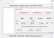
Folding 2 80mm double "coil" membranes
One with 6my mylar and one with 3m 74 tape app 12my mylar.Alu 40my tape.

Her the latest drawing with one more "turn"
Picture with better quality in the gallery.
Bernt

This is one of the best decisions
- Status
- Not open for further replies.
- Home
- Loudspeakers
- Planars & Exotics
- Diy AMT