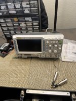
Hello to all on this forum. I would like to know if any of you would be interested in guiding me through testing my recent diy Aleph j build. I have just purchased my first scope and it really seems like a sh---t load of knobs and buttons. The amplifier I am trying to test has 400mv bias on both channels and close to 0 offset, it does play music. I would like to do a performance check on it. I have added some pics of my build and the o-scope I purchased . would appreciate any help thanks.
Attachments
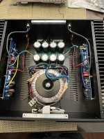


Your build looks very good. The bias and offset readings mean the amp is performing really well.
As to the oscilloscope... get a tone generator (either a proper hardware box.. with maybe triangle, squarewave and sinewave options, or a software app) and then play with the scope... learn the basics and then move to play with your Aleph J... like, you could check the symmetrical clipping unloaded and loaded, or you could even tune the feedback capacitor (5pF) for that perfect looking squarewave... at lats say 10kHz. Just make sure you will not stress Aleph J too much when testing.... Oh, yes... you could also confirm that the amp is stable... i.e. that there are no oscillations... with and without the load.... you could also see what happens when you place the load at the end of your speaker cables.... or, you could apply a bit of capacitive load (start with 0.1uF) in parallel to the resistor load, and see what happens.
Once again, make sure that you do not stress Aleph J too much... sine waves, and in particular the square waves, are not meant to be fed to an amplifier while it is working at full power output.
There you go, plenty to do.
Ok, thanks. yes, that is plenty, but I have limited experience with electronics and I really put this amplifier together with the posted help-build articles and a little common sense. knowing what's actually happening is a different story. for a beginner hobbyist all that you said up above is a lot to digest so I would need something more step by step. let me put it this way. if you had just finished this amplifier build yourself what would be the next thing you would check besides the bias and offset?
This is a good thread with information on how to measure distortion:
https://www.diyaudio.com/community/threads/how-to-distortion-measurements-with-rew.338511/
You might consider this at some point in the future.
https://www.diyaudio.com/community/threads/how-to-distortion-measurements-with-rew.338511/
You might consider this at some point in the future.
Well, for starters... get the tone generator and then see how different waveforms, at different frequencies, look on the scope.... you'll learn about time-base and peak-to-peak values' settings.... also, about AC vs DC settings/probe coupling... Also, you'll figure out what 1:1 and 1:10 probe settings do. This will give you a starting point...
Ah, yes -> you could look for + and - voltage rails ripple.... maybe try a couple of inductors instead of the resistors in the power supply, and see what that does to power rails ripple.
If you are planning to tinker, always do only one thing at a time, and then give yourself plenty of time to listen... before you attempt to mod something else. Otherwise, you'll confuse yourself.
Having a reference quality amplifier (something to compare the mods to...) is desirable, but expensive.
Last edited:
ok, thanks, so I think I may need a way to inject a signal into the amplifier to view a waveform.? ..... what would a basic hook-up look like? would I connect the signal generator to the o-scope and then to the amplifier or the signal generator to an amplifier and o scope to the amplifier?
- Home
- Amplifiers
- Pass Labs
- diy Aleph J testing?