I thought I'd post my method up here in case it's useful.
Playing with some class-D amp I thought it would be useful to make my own inductors, because they are only made of bits of wire and that's much cheaper than buying them right?
So I played with a bit of old toroid with 1.2mm wire until I realised that I needed a bobbin to hold it all together, or at least a former and some superglue.
Then I found a useful guide to them HERE.
gifs upload
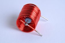
So the bobbin's I chose are regular sewing bobbins, in plastic, mine measure 8.5mm dia in the middle and a length of 9mm for the coil.
I decided on AWG21 (0.72mm) wire giving a 0.05ohm DC resistance for a 10uH inductor needing 38 turns. Thicker wire will fit in but this is dead easy to manage and I only bought this one size. The design tool posted above gives you all the sizes if you want to try thicker wire - next time I'd probably go up one or two sizes, you'd also need less turns if you did.
After mounting the coil of wire (a 500g reel) in my solder dispenser I hand fixed an M6 bolt in the reel, set the drill on slow and 'backwards/undo' to wind the coil.
Using my finger and thumb to tension and guide the wire I just had to count to 38 and it was wound, and after about 5 minutes I had 4 nice inductors that actually measured exactly the same inductance as my 10uH Wurth ferrites I'd bought.
Note: Run the drill back as it self-tightens the bolt in the bobbin, go forward and it will just loosen off.
An additional advantage to winding your own is you can make the flyleads as long as you like, which makes soldering them in much easier and allows you to have less PCB track around gathering capacitance.
Probably best to mount them at right angles to each other as the flux is not so constrained like in a ferrite so you may get a little crosstalk. However you'll never saturate the cores and air is pretty linear so they should sound good.
Playing with some class-D amp I thought it would be useful to make my own inductors, because they are only made of bits of wire and that's much cheaper than buying them right?
So I played with a bit of old toroid with 1.2mm wire until I realised that I needed a bobbin to hold it all together, or at least a former and some superglue.
Then I found a useful guide to them HERE.
An externally hosted image should be here but it was not working when we last tested it.
gifs upload
So the bobbin's I chose are regular sewing bobbins, in plastic, mine measure 8.5mm dia in the middle and a length of 9mm for the coil.
I decided on AWG21 (0.72mm) wire giving a 0.05ohm DC resistance for a 10uH inductor needing 38 turns. Thicker wire will fit in but this is dead easy to manage and I only bought this one size. The design tool posted above gives you all the sizes if you want to try thicker wire - next time I'd probably go up one or two sizes, you'd also need less turns if you did.
After mounting the coil of wire (a 500g reel) in my solder dispenser I hand fixed an M6 bolt in the reel, set the drill on slow and 'backwards/undo' to wind the coil.
Using my finger and thumb to tension and guide the wire I just had to count to 38 and it was wound, and after about 5 minutes I had 4 nice inductors that actually measured exactly the same inductance as my 10uH Wurth ferrites I'd bought.
Note: Run the drill back as it self-tightens the bolt in the bobbin, go forward and it will just loosen off.
An additional advantage to winding your own is you can make the flyleads as long as you like, which makes soldering them in much easier and allows you to have less PCB track around gathering capacitance.
An externally hosted image should be here but it was not working when we last tested it.
An externally hosted image should be here but it was not working when we last tested it.
An externally hosted image should be here but it was not working when we last tested it.
An externally hosted image should be here but it was not working when we last tested it.
An externally hosted image should be here but it was not working when we last tested it.
Probably best to mount them at right angles to each other as the flux is not so constrained like in a ferrite so you may get a little crosstalk. However you'll never saturate the cores and air is pretty linear so they should sound good.
Great. You can watch them heating up at idle.
Not to mention the fun of wiping out every radio in the neighborhood. 😀
Not to mention the fun of wiping out every radio in the neighborhood. 😀
If you think that then I suggest you read this, from 4 years ago:
http://www.diyaudio.com/forums/class-d/237086-tpa3116d2-amp-586.html
Last edited:
I thought about rolling my own inductors but the hassle and expense of getting magnet wire and winding it or not worth it. Easier and cheaper to buy low cost ones from China. I can get a bag of 20 ferrite core radial lead inductors of typical values for a few dollars. Btw, these same inductors in the 1mH range are also very cost effective low power audio filters - rather than buying $15 18ga air cores. For some full range speaker applications where you never use more than 5 watts or so a $0.50 inductor works just fine for a baffle step comp circuit.
I thought they were impossible too, as I was trying to achieve this:
(The SMSL SA-60 pictured).
Then the calculator kept telling me to go wider and flatter, so I tried a nut and couple of washers before I realised that a sewing bobbin <obiwan>was the item I was looking for</obiwan>.
Winding them into a bobbin was in fact ridiculously easy 😀
(The SMSL SA-60 pictured).
Then the calculator kept telling me to go wider and flatter, so I tried a nut and couple of washers before I realised that a sewing bobbin <obiwan>was the item I was looking for</obiwan>.
Winding them into a bobbin was in fact ridiculously easy 😀
I like the idea of the sewing bobbin. I recognized those as soon as I saw your pictures.
In general, you get the most compact inductor for a given inductance if it's roughly square. I.e. length = diameter. I use an AA battery for the inductor in the Thiele network in my Modulus-86.
Tom
In general, you get the most compact inductor for a given inductance if it's roughly square. I.e. length = diameter. I use an AA battery for the inductor in the Thiele network in my Modulus-86.
Tom
Attachments
Very neat! I like the resistor holding it all together too.
I'm not sure how much ferrites distort but the lines don't look that linear to me.
http://www.farnell.com/datasheets/1951886.pdf
I hear that people say that Alnico speakers sound sweeter than ones with ferrite magnets in for the same reason: linearity, hysteresis etc, etc.
Plus people like the sound of the SA-60 which is often described as 'sweet'.
No reason on my workbench not to use the most linear components, even if it involves counting to 38 🙂.
BTW: I did some simulations with 20uH and 15uH for filters, but ended up with 10uH as the best for 4, 8 and 16 ohms, perhaps due to a simulation error on my part 😉. I ended up with LC of 10uH/220n with a common mode RC 220n/22R, which I have tried and sounds good to me for both my speaker sets (Grundig 4ohm and some 8ohm ones).
upload pics
I simulated this on Online Circuit Simulator with SPICE as it saves downloading and faffing about, I guess a few here use it too. It gives a great response for 4-16ohms, which allows a few dips and peaks in a speaker's impedance.
Anyway as I'd settled on 10uH which is pretty small I felt sure it could be wound without too much trouble, it's not like making an input transformer!
YMMV, I'm sure others will use their favoured ideas - I only posted up to help those who wanted to try some air cores. Plus it's more DIY than buying in 😀
I'm not sure how much ferrites distort but the lines don't look that linear to me.
http://www.farnell.com/datasheets/1951886.pdf
I hear that people say that Alnico speakers sound sweeter than ones with ferrite magnets in for the same reason: linearity, hysteresis etc, etc.
Plus people like the sound of the SA-60 which is often described as 'sweet'.
No reason on my workbench not to use the most linear components, even if it involves counting to 38 🙂.
BTW: I did some simulations with 20uH and 15uH for filters, but ended up with 10uH as the best for 4, 8 and 16 ohms, perhaps due to a simulation error on my part 😉. I ended up with LC of 10uH/220n with a common mode RC 220n/22R, which I have tried and sounds good to me for both my speaker sets (Grundig 4ohm and some 8ohm ones).
An externally hosted image should be here but it was not working when we last tested it.
upload pics
I simulated this on Online Circuit Simulator with SPICE as it saves downloading and faffing about, I guess a few here use it too. It gives a great response for 4-16ohms, which allows a few dips and peaks in a speaker's impedance.
Anyway as I'd settled on 10uH which is pretty small I felt sure it could be wound without too much trouble, it's not like making an input transformer!
YMMV, I'm sure others will use their favoured ideas - I only posted up to help those who wanted to try some air cores. Plus it's more DIY than buying in 😀
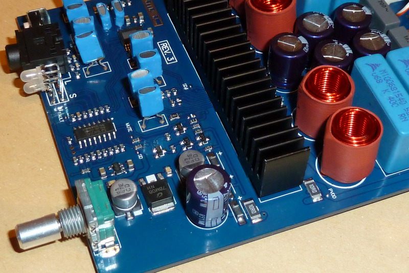
I've always wanted to experiment with the style of inductor on some of the ICEPower modules. Both halves of the bridge are wound on a single gapped toroid.
You can see it in the upper left of this pic...
You can see it in the upper left of this pic...
An externally hosted image should be here but it was not working when we last tested it.
In general, you get the most compact inductor for a given inductance if it's roughly square. I.e. length = diameter.
Not really. To be more precise: your statement is underdefined. You didn't tell anything about 1: resistance, 2: weight. 3: number of layers.
For a given inductance and given DC resistance and lowest weight but without specifying fixed number of layers the best geometry is actually very close to a fully wound sewing machine bobbin. But for low AC loss it is very bad. Generally: the more compact the design the higher the eddy current loss.
Your rule apply more or less for single layer inductors. However "compactness" is not a well defined parameter. What should be minimal? Surface? Volume?...
I guess one could wind each layer on the bobbin and then add a tape spacing layer before the next coil layer.
Either way I suspect in practice it may not matter much, getting rid of the ferrite is for me the main aim.
The real discovery for me was how easy and quick it was to wind my own. Next comes the trials and experiments 🙂.
Basically in a class D we rely on accurate switching (a decent chip + snubbing) and we actually listen to the output filter, which is why I chose to try air-cored with polypropylene (Panasonic) caps.
EMI:
I was also reading about the AM ferrite antenna that are used in AM/MW radios, and wondering why ferrite cored inductors driven in the AM band (which is what the TPA3116 does to them) doesn't create a good transmitter.
The conclusion was that it doesn't for the same reason that the air cored inductors are not aerials either - because we are creating a local magnetic field: not an electro-magnetic one, so it can only interfere at a very close range.
So I wouldn't stick a class D amp next to your ferrite rod AM tuner, but don't worry about transmitting an EM wave out of the room/box as there is no E.
Also, interestingly enough, an AM aerial receives only from the sides, point the rod at the transmitter and you get no signal at all. That's because the magnetic component of the vertically polarised AM signal is a horizontal side-to-side wave so to tap into that the rod must be side on to the transmitter.
Anyway, I'll not bore the reader with any more basic physics, I have stuff to wire up 🙂
Great work! Looking forward to your results as you try different values of L and C (down to zero?)
Cheers,
Mike
Cheers,
Mike
I guess one could wind each layer on the bobbin and then add a tape spacing layer before the next coil layer.
Either way I suspect in practice it may not matter much, getting rid of the ferrite is for me the main aim.
The real discovery for me was how easy and quick it was to wind my own. Next comes the trials and experiments 🙂.
Basically in a class D we rely on accurate switching (a decent chip + snubbing) and we actually listen to the output filter, which is why I chose to try air-cored with polypropylene (Panasonic) caps.
EMI:
I was also reading about the AM ferrite antenna that are used in AM/MW radios, and wondering why ferrite cored inductors driven in the AM band (which is what the TPA3116 does to them) doesn't create a good transmitter.
The conclusion was that it doesn't for the same reason that the air cored inductors are not aerials either - because we are creating a local magnetic field: not an electro-magnetic one, so it can only interfere at a very close range.
So I wouldn't stick a class D amp next to your ferrite rod AM tuner, but don't worry about transmitting an EM wave out of the room/box as there is no E.
Also, interestingly enough, an AM aerial receives only from the sides, point the rod at the transmitter and you get no signal at all. That's because the magnetic component of the vertically polarised AM signal is a horizontal side-to-side wave so to tap into that the rod must be side on to the transmitter.
Anyway, I'll not bore the reader with any more basic physics, I have stuff to wire up 🙂
Can't speak for others, but this is exactly the kind of post I like to read on the internet.. As a struggling hobbyist (but obsessive modifier/builder) just learning this stuff, posts like this help me convert theory i know or am learning and incomplete statements i read on the internet into actual useful knowledge. Often the most significant "Ahhhh! I see now!" moments are caused by the almost conversational addition of other information. Thankyou.
Last edited:
"But for low AC loss it is very bad"Not really. To be more precise: your statement is underdefined. You didn't tell anything about 1: resistance, 2: weight. 3: number of layers.
For a given inductance and given DC resistance and lowest weight but without specifying fixed number of layers the best geometry is actually very close to a fully wound sewing machine bobbin. But for low AC loss it is very bad. Generally: the more compact the design the higher the eddy current loss.
Your rule apply more or less for single layer inductors. However "compactness" is not a well defined parameter. What should be minimal? Surface? Volume?...
Could you explain this?
I asked some while ago how we could make low capacitance air cored inductors, but got no replies. Is capacitance what you are referring to?
There is no gnd at the speakeroutput. Simulation is easiest for single ended half of filter with half speaker impedance, the amps are BD modulation, not AD, TI suggests not to use any filter components between the outputs other than speaker ofcourse.
http://www.ti.com.cn/cn/lit/an/sloa119b/sloa119b.pdf
http://www.ti.com.cn/cn/lit/an/sloa119b/sloa119b.pdf
Very neat! I like the resistor holding it all together too.
I'm not sure how much ferrites distort but the lines don't look that linear to me.
http://www.farnell.com/datasheets/1951886.pdf
I hear that people say that Alnico speakers sound sweeter than ones with ferrite magnets in for the same reason: linearity, hysteresis etc, etc.
Plus people like the sound of the SA-60 which is often described as 'sweet'.
No reason on my workbench not to use the most linear components, even if it involves counting to 38 🙂.
BTW: I did some simulations with 20uH and 15uH for filters, but ended up with 10uH as the best for 4, 8 and 16 ohms, perhaps due to a simulation error on my part 😉. I ended up with LC of 10uH/220n with a common mode RC 220n/22R, which I have tried and sounds good to me for both my speaker sets (Grundig 4ohm and some 8ohm ones).
An externally hosted image should be here but it was not working when we last tested it.
upload pics
I simulated this on Online Circuit Simulator with SPICE as it saves downloading and faffing about, I guess a few here use it too. It gives a great response for 4-16ohms, which allows a few dips and peaks in a speaker's impedance.
Anyway as I'd settled on 10uH which is pretty small I felt sure it could be wound without too much trouble, it's not like making an input transformer!
YMMV, I'm sure others will use their favoured ideas - I only posted up to help those who wanted to try some air cores. Plus it's more DIY than buying in 😀
Great work! Looking forward to your results as you try different values of L and C (down to zero?)
Cheers,
Mike
I'm not sure zero filter or zero caps is an option with a speaker lead, but people have said that 100n sounds rather nice! Here's 220n and what it does to the response at various impedances.
An externally hosted image should be here but it was not working when we last tested it.
An externally hosted image should be here but it was not working when we last tested it.
An externally hosted image should be here but it was not working when we last tested it.
actual useful knowledge
Thanks Skree, glad something I write is useful 🙂
There is no gnd at the speakeroutput.
Thanks Irribeo, however I'd like to gently point out that simulators don't have a ground either 😉.
It's a arbitrary reference point to make the maths work as it anchors the conductance grid so it can be loaded into the sparse matrix for solution.
I had to put the 0V point there as I wanted to know the magnitudes of a half (common in the diagram, inverted), and the speaker output. As partsim doesn't have a 'voltage between this and that' shifting the 0v is quite valid.
There may still be something wrong with the simulations, but it's not the 'ground' 🙂
- Home
- Amplifiers
- Class D
- DIY air cored inductors (how I made mine).