I'm using ACA mini as a headamp and am using 25K. The 50K I had on it initially killed the dynamics.Thank you Nelson! I assume plain 10-50K pot before the input cap is what I need.

Question about bias procedure.
I just finished my unit with the essential kit and supplied my own parts. I got the PSU today, fired up, no smoke.
upon measuring between VO and ground I automatically get 11.5 volts on both sides. But I do see 0 between the VB locations.
Under the impression I should see 0 for both. Any help is appreciated
If you have 0 volts VB, that means no current through r8 and output transistors.
Heatsinks are cold and sound is very distorted.
Unless you do not measure right. VB is not measured against the ground. Its the voltage on the resistor.
Start with all pots in the middle, then slowly turn right step by step both alternatively.
Instructions in the manual are impecable.
Heatsinks are cold and sound is very distorted.
Unless you do not measure right. VB is not measured against the ground. Its the voltage on the resistor.
Start with all pots in the middle, then slowly turn right step by step both alternatively.
Instructions in the manual are impecable.
Last edited:
Question about bias procedure.
Under the impression I should see 0 for both. Any help is appreciated
Read the instructions, VB should be 0.3 volts.
Instructions are in pdf article on first watt webpage.
Kevin Heemstra made these videos going over the process.Question about bias procedure.
I just finished my unit with the essential kit and supplied my own parts. I got the PSU today, fired up, no smoke.
upon measuring between VO and ground I automatically get 11.5 volts on both sides. But I do see 0 between the VB locations.
Under the impression I should see 0 for both. Any help is appreciated
Check these out:
If any question remains about where to measure Vb, the very clear diagram provided by Charles Port in post # 1068 (here) shows connection points graphically for the left channel.
(Note though that for the V0-GND measurement, Charles chose to use a speaker ground for GND, which is equivalent to the labeled GND point at the lower-right of the PCB).
I'll also note that I did not see any voltage across the Vb pairs until I got well past half way (12 o'clock) on the pots. Final settings were at about 3 o'clock on the pot dials (I'm talking about general position of clock hands, not the tiny markings on the pots, which I can't read).
Nelson, is it possible to make a lower watt version of the amp? I know it is kinda unusual, but I am using it with 98db speaker and 1-2W would be ideal as I am running my volume pot all the way down with this power beast at the moment 🙂I think the Input jfets would be happy at as high as 50K pot, but if you are concerned, then 10 to 25 is fine.
Tried lower power supply? (I am not Nelson, i know)
Generally power of the amplifier rises with increasing voltage of power supply.
Generally power of the amplifier rises with increasing voltage of power supply.
From my previous experiments with F5, just lowering the rails was affecting sonic characteristics of the amp. Unfortunately I don't know how to run sims to check this out. How low should I go without messing the whole operation and characteristics of the circuit?
Please, I welcome any assistance from any member of the forum (at the same time, of course, we always hope to get the response from the man himself with ZM being the second best haha) 🙂. There are so many bight people here, maybe not as good as Pa, but way way sharper than myself 🙂
Please, I welcome any assistance from any member of the forum (at the same time, of course, we always hope to get the response from the man himself with ZM being the second best haha) 🙂. There are so many bight people here, maybe not as good as Pa, but way way sharper than myself 🙂
in this case . rail is sorta on the verge to still have mosfets moderately happy
if you need lower power, decrease Iq, decrease gain
though, describe rest of your source - amplification chain ..... it could happen that you have excessive gain, more likely than excessive power
sayin' that, even if my most used setup can't go above 750mW@16R and I'm more than happy with it, most of the time
It is actually a continuation of our brief discussion in the F4 thread. I am reamping my guitar tube head. So it is 20W tube amp --> 8R resistor --> 10k pot --> ACA mini --> guitar speaker. I know you were saying that class D amp and all that. I tried it and class A amps just sound better even in this application, less grainy more like a direct tube amp into the speaker.

Then you need just one more voltage divider instead of 8R. Just like I did when i wanted to use tube amp for headphones.It is actually a continuation of our brief discussion in the F4 thread. I am reamping my guitar tube head. So it is 20W tube amp --> 8R resistor --> 10k pot --> ACA mini --> guitar speaker. I know you were saying that class D amp and all that. I tried it and class A amps just sound better even in this application, less grainy more like a direct tube amp into the speaker.
I suggest 8R + 1R, amp will see 9 ohms, take live signal out from 1R. You get 1/10th signal out. Or use 4 + 4 ohms. Get half signal.
No need to mess with aca mini.
Oh yes! Thank you for sharing and thanks to Kevin for making this!Kevin Heemstra made these videos going over the process.
Check these out:
Thank you so much!Then you need just one more voltage divider instead of 8R. Just like I did when i wanted to use tube amp for headphones.
I suggest 8R + 1R, amp will see 9 ohms, take live signal out from 1R. You get 1/10th signal out. Or use 4 + 4 ohms. Get half signal.
No need to mess with aca mini.
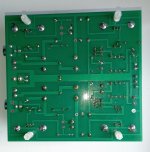
Help!! I completed my amp at the weekend but all 4 heatsinks are cold after power up. I can adjust values for Vb but there is no drift from these once set. I can also adjust Vo to around 11.5v no problem. Can anyone point me in the right direction to begin fault finding??
Attachments

Kevin’s video of the bias set up was VERY helpful to me setting bias.Help!! I completed my amp at the weekend but all 4 heatsinks are cold after power up. I can adjust values for Vb but there is no drift from these once set. I can also adjust Vo to around 11.5v no problem. Can anyone point me in the right direction to begin fault finding??
The amp will be cold until you set it correctly.
You will want two Digitial meters.
Adding a few posts to clip the meter leads to helped me.
- Home
- Amplifiers
- Pass Labs
- DIY ACA mini