I second TPS7A4901/TPS7A3001 recommendation. I use them in all of my projects. I can also recommend using isolated DC-DC converters with post regulation using a pair of LDO regs. The DC-DC converter can be powered using a battery pack or a USB charger. This eliminates the mains earth connection and thus reduces the chance to create a ground loop. On top of that it also eliminates the need to work with the mains voltage directly which is one of the most dangerous parts of the diy audio.
Regards,
Oleg
These are the post-switcher linear regs in the silentswitcher.
Jan
Thank you Rayma, so I wouldn't be reducing heat unless I actually also dropped the voltage going into the LDO regulators?
Of course there is always a problem with a LDO. As the line Voltage shifts around (and it DOES - a LOT.
On a HOT day in California I've seen the line drop from 120 to 99 Volts) the drop across the regulator varies
so the thermal output is unpredictable. This is worse for low voltage supplies like the 5V and 3.3V in computers.
In the late '60s early '70s Ampex dealt with that in VTRs. They did a primitive switching supply using SCRs
in the rectifiers. To keep the control linear they used a cosine ramp rather than a linear ramp in the
comparators to get the variable phase SCR trigger pulses. These machines used large amounts of power.
The AVR-1 and ACR-25 ran 208 Volts. The switching section would make +/- 15 which then went to +/- 12
linear regulators which now had a constant 3 Volt drop and constant thermal power regardless of line voltage.
The same was done for the 5V and 24V supplies. You got the clean DC from the linear regulators with the
benefits of a switcher.
Back to your LDO. You could uses a modern switcher ahead of the LDO but this is most effective when
using significant power. Inside a low power preamp the easiest solution is to use a larger heatsink and
enjoy the music.
Happy New Year
G²
I am one of those dinosaurs who has my drawers full of LM317/LM337/78xx/79xx and TL431. I therefore normally design my own voltage regulator circuits. But, some time ago I noticed a good looking LM317/337 board at a price I could hardly make a simple copy: GHXAMP LM317 LM337 Servo Rectification Filter Power Supply Board AC to DC NEW|Amplifier| - AliExpress .
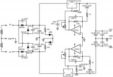
I bought one and tested it statically on arrival – it seemed to work. About two weeks later I decided to analyze the seemingly not fully trivial circuit by drawing-up the circuit. The schematic is appended. I have before had “surprises” with unknown boards, and here I had one good discovery and one important restriction.
The circuit includes dynamic noise canceling (active noise filter) using an LF353 OP-AMP. The restriction I found is, as the LF353 is supplied directly from the LM317/337 outputs, the output voltage should be kept below +/-18Vdc or the LF353 may suffer damage. In case more than +/-18V is needed, the LF353 has to be taken out of the IC socket and pins 1 and 7 of the socket connected to ground. This way the dynamic noise canceling is disabled and the LM317/337 circuits work the normal way. Due to a twisted ankle, I have not had the occasion to check the dynamical noise canceling performance.
My conclusion is that this is a very suited and cheap board for those who like experimenting with OP-AMP circuits. OP-AMP circuits normally operate from +/-5V to +/-17V and the board can be adjusted (trim-pot) for that voltage range. Connecting a 7K5 resistor across each of the 5K trim-pots will limit the output voltage to +/-17.5V, disregarding a higher input voltage. I use my board with a +/-15Vac 30VA transformer but a 50VA transformer should be used for full current capacity (be aware of sufficient cooling).
I know that the forum has members who are far ahead of LM317/337 performance, so for them please disregard this posting. But, hardly anything can beat the value-for-money ratio of this board.
Attachments
Last edited:
Sidenote: opamp circuits in (digital) audio in general should be fed with higher voltages than +/- 5V.
Today I had time to make a simple noise test of the LM317/LM337 board I mentioned in posting #23. With +/-12Vdc output voltages, 47 Ohm or 470 Ohm loads at the outputs and a 2x15Vac-30VA transformer at the input.
I used my Hameg oscilloscope with full AC-gain (1mV/division) to look at the outputs. With both load values and judging from my oscilloscope screen, the noise above 1Hz is better than 50uV RMS. Thus, an improvement of the LM317/LM337 standard performance.
Absolutely sufficient for most OP-AMP constructions.

Hi guys,
You've complained to me about shipping cost when getting a Silentswitcher from the diyaudio store.
While that is not something we can do anything about, Jason agreed to slice $ 10 off the price to sweeten the deal a bit.
Effective now.
Thank you Jason & diyaudio.com store staff!
Jan
You've complained to me about shipping cost when getting a Silentswitcher from the diyaudio store.
While that is not something we can do anything about, Jason agreed to slice $ 10 off the price to sweeten the deal a bit.
Effective now.
Thank you Jason & diyaudio.com store staff!
Jan
I know that the forum has members who are far ahead of LM317/337 performance, so for them please disregard this posting. But, hardly anything can beat the value-for-money ratio of this board.
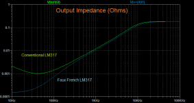
The output impedance of the circuit you illustrated is very significantly better than the conventional LM317 circuit. If I recall, this was also demonstrated by El Vee's noise reduction circuit which gains up the LM317.
Attachments
Hi guys,
You've complained to me about shipping cost when getting a Silentswitcher from the diyaudio store.
While that is not something we can do anything about, Jason agreed to slice $ 10 off the price to sweeten the deal a bit.
Effective now.
Thank you Jason & diyaudio.com store staff!
Jan
Nice project Jan, are you making a schematic available for this?
- Home
- Amplifiers
- Power Supplies
- DIY +/-15V - Anything more efficient than LM317/LM337?