thanks I will give that a look
My reasoning on trying a more pistonic (aluminum) 12-15 ich woofer has to do with past experiences using a 13 inch wide planer as a woofer years ago mated to a long true ribbon at the side. Similar to an Apogee design. The woofer was a tad directional IMO crossed at 400 hz ( 6db gradually increasing to 12 db) but not bad. You had to get toe in right to get its best . However the big planer woofer seemed be the star of the show because of how it traversed the region from about 200 to 1.5 khz. Beautifully smooth, BUT So were some large heavy well damped cones of similar width. however they didnt come close to same class as the big planer woofer in the midrange despite the fact they measured low distortion and similar of axis
I was reading in Martin Colloums book "High perf loudspeaker s" years ago that there seems to be a subjective uglyness with doping and high loss materials in loudspeakers despite smooth FR. A loss of clarity and a type of distortion perhaps related to the hysteresis that goes with using mechanical damping to smooth response. I did a ton of development on the free swinging ribbon to this effect trying to get that subjective clarity that the foil ribbons had BUT get some of the sweetness that the doped (plastic/ adhesive/ foil combo) ribbon designs had. I landed on a compromise that retains much of each types strengths.
today as a test I ran the planer to 200 hz rather than 350. The planer is curved now and has the typical dividing strips like the martin logans to hold shape. These smaller "cells" ( about 3 inches wide, allowed me to tune the smallish planer ( about 12 inches square) to a main resonance of about 180 hz. With some acoustic resistance out back ( cloth glued to magnet screen) the peak is rounded off and it has a fairly strong response now down to 200hz
From there I ran the big woofers up to 200hz.
Easily better than at 350hz. maybe lacking a small amount of "meat" on her bones but overall usefully better sonic.
anyway thanks for the tip and the link. I will give it a look
Potentially relevant commentary below. I've seen similar discussions regarding formers, glues, etc., and higher rigidity materials in those components producing more detail. Can't find the primary one I was thinking of though.
http://www.troelsgravesen.dk/HES/JGerhard.doc
"What many driver manufacturers have done the last years, is to increase the damping to make the frequency response more flat. But some old drivers, like the famous 6,5" paper woofer that Jan Paus at Seas made several years ago, (The Seas CA 17 RCY, ed. note) was optimized for low loss. So they made a compromise between frequency response and sensitivity. This driver was very good, and was used by Wilson Audio for many years. Later, in the 80's, manufacturers started to add more mass, they added more damping, and they made surrounds with high loss. That gave an extremely flat frequency response, but also a lot of energy storage. This compared, the old drivers were much quicker. They had some resonances, but you could get rid of that in the crossover. It was this run for flat response that gave a lot of modern drivers this dull, uninteresting sound. And you can also measure higher second and third harmonic distortion in some of them. If you compare the on-axis response between an old and new driver; you will see that the energy in the treble is far higher than in the new drivers. These so-called "modern" drivers often has a Qms of maybe 0.8 or 0.6. The old drivers had Qms values of maybe 5 to 7! We found that drivers with a very high mechanical Q sound more open, more clean and dynamic. And when you look at it, you find it is very simple, because they have less loss. The surround is easier to move, the spider is better constructed, they have better air flow, higher sensitivity. So a high mechanical Q is a very good indicator of energy storage behavior. This is one of our secrets. One of the many!"

yes exactly!!
Fun story
I modded an old radio shack Ha! light weight 15 inch woofer once. It was just a thin steep angled polypropylene woofer with a high loss surround. Bass was ho hum. I shellacked the surround with a layer of silicone calk. The Qms went up considerably and the bass was transformed. I mean I would NEVER have believed it would make that much difference in the bass dynamic. We mounted it in the trunk of my daughters car behind rear seats on just a plywood wall using entire trunk as box. . All the boys with their huge heavy subs in boxes were jealous and could not believe how much better her cheap cobed together sub sounded. It didnt go low, maybe 40 hz BUT it was far more musical. Fast dynamic and alive
I then took a similar driver, an 8 inch version of the same and instead of coating the surround ( i wanted to keep as much mid freq termination of the high loss surround as I could) I instead ran some 20 lb test monofilament fishing line through two small holes melted in cone down by the VC and tensioned the filament on some spars epoxied to the magnet structure. The Qms went up and the bass became exciting similar to the 15 inch with the low loss silicone surround
Yes the Fs was up a bit on each BUT tests with other woofers with similar Fs simply did not have the same subjective bass quality
I swear I hear the same subjective effect on voice and treble on the foil only ribbons verses the plastic backed units BUT why??
BTW talk about dynamics and the subjective character of low loss systems. The planer im working, when the diaphragm is set at about 200 hz Fs and the woofer crossed hard there, it has a seriously visceral percussive impact.
I suspect much of the sharp in the chest feel is centered around info in the 200 hz area ? Theres no "bump" in the response curve I can see but damn it rocks ha. I havent looked at the CSD yet
Perhaps this is all related to the often noted connection between high sensitivity and clarity or dynamics or snap or whatever you want to call it. From a simple-minded perspective, low sensitivity and high amplifier power might get you to the same place as high sensitivity and low amplifier power, but a ton of people say no. I wonder if some of the newly identified distortions that the folks at Purifi have found ways to address (hysteresis in the magnet system, nonlinearity in the surround, etc.) might also be part of the answer. Do high sensitivity drivers just take a different approach to reducing the hysteresis in the magnet structure? I won't claim to have the answer.
Few
Few
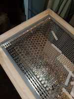
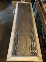
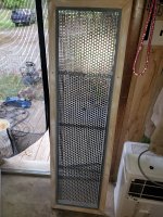
Maybe this was asked already, what type of magnet structure are you running? I have built a set of 12" X 48" panels with full neodymium magnets. And 3mm xmax. I have to roll off my lows, 50hrz. And down. My panels want to make bass.
Attachments
Jasonkilo
Im using same basic magnet layout as you have to the left side of your panel
could you explain why you are using round magnets for the rest of the panel. I assume that will be the woofer section?
also curious what adhesive you are using to fix the magnets
Im using same basic magnet layout as you have to the left side of your panel
could you explain why you are using round magnets for the rest of the panel. I assume that will be the woofer section?
also curious what adhesive you are using to fix the magnets
Sure, cost, and air flow . The small 10mmx3mm disks are much cheaper than the bars, and cover less area. I calculated my panels have 51% open air to the rear. Unfortunately there is also 1000+ per panel. And first I placed each magnet. The a drop of super thin super glue, or CA glue. After that a heavy coat of paint, then wiped the top of the magnets off. Time consuming for sure.
Attachments
The disks also cause the magnetic feild to zig zag at a 45 degree angle. Which I feel helps with output. Always pulls foil across a hole in the steel backer.
Mind if I ask, how are you stretching your mylar? I'm currently using the pull, and pray, method. Need to come with a system to measure how much stretch is being applied.
thanks
yea the thin glue "wicks" right under the magnets nicely. These types of adhesives are a bit brittle and fragile to bending stress. Ther are so called "toughened" versions but I have not experimented with them and not sure if they come in the thin viscosity
The small planer Im working now isnt too critical of exact tension because its used well out of the main resonance AND its a prototype test bed so to speak so for now the tensioning is done by hand. The panel is curved so its just massage the diaphragm into place with double side sticky tape at edges. Its designed to remove and replace often for test purposes as I alter the panels curve radius
In the past however I have built larger units as woofers similar to what ya have there and the main tune is critical. In that case I use a hand held weigh scale to apply tension to many tapes around diaphragm edges as diaphragm is layed down on flat surface. I just go around entire perimeter of diaphragm tensioning each tape individually. Depending on size of diaphragm and mass of foil , the exact main resonance ya want you have figure out by trial and error. I think I had about 30 tapes round a 12 inch by 30 inch panel each one tensioned to around 5 lbs of pull. Thats a guess, its been years and not certain. This gave around 45 Hz main tune on 1/2 mill film and 1 mill foil
BTW as for the "air movement" through the magnets/ steel screen. On planer woofers you will have a very high resonant rise at main tune and the way to control that is the open area of the magnet/screen structure. Yours will likely be a bit too "open" and the bass rise may be excessive. I usually tune bass diaphragms by actually closing off the openings a bit by gluing felt or thin cloth to back side of magnet / screen structure. Often that rise in bass response will be about 15-20 db at resonance BUT you can damp it down to where ya want ( usually only need about a 10db rise or less ) by closing the open area off a bit. This will tighten up the bass and give considerable control to excessive diaphragm movements as well as tame some of the standing wave activity in the 200 hz region that often is a trouble area for planers
I believe most commercial planer woofers have only about 10-12% open area. If I was to guess yours looks much higher than that. maybe as much as 30%
I'll have to give that a try. I figured I could restrict air movement, but kind of hard to add it. I have tried blocking off sections of the back with tape. But always messed with the frequency response in a way I didn't like. Maybe a thin felt or cloth, to just slow it would be better
I used a pneumatic stretcher to replace diaphragms in Quad ESL-63s. It allows measurement and even tuning of the resonant frequency before gluing the film to a frame.
pneumatic diaphragm stretcher
I test resonance by tilting the tensioned diaphragm up vertically and then bouncing a ball bearing hanging from a thread against it. I Use a UMIK-1 mic and the RTA in REW to read the resonance. Resonance is tuned by adjusting the air pressure in the bicycle tire tube that surrounds the stretcher. Once I get the desired resonance, I apply glue to the film and the frame, wait 20 minutes, and put the two together. I use 4693H contact cement that forms a strong bond to the polyester film (unlike the stuff Quad used).
resonance testing
The pneumatic stretcher will allow tension up to the burst strength of the film.
I will look into building one of these. Only issue is size, my frames are 15" X 51" outside. May have to use 2 inner tubes?
- Home
- Loudspeakers
- Planars & Exotics
- distortion question for you planer makers