HELP!!!
I've built this pedal, and I cant identify what's wrong.

If both pre-gain and gain are turned up, a steady, fast ticking noise appears, or a loud high pitched whistle, depends on which one is turned up first, with no signal from the bass coming through. With both these knobs turned down, the signal can be heard, undistorted, quiter than when the circuit is bypassed. The bass signal could be heard with the volume turned down, but the before mentioned issues appear when the volume is up, so i just removed it until i solve the issue.
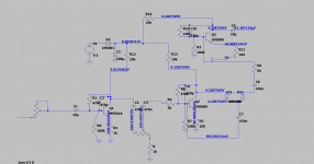
I've built an LTspice simulation to compare voltage values, and these are the main points:
1.voltages before the collectors of Q1 and Q2 are identical in the simulation, 4.228.. , but it's 4.9 and 4.16 in my circuit
2. Voltages before and after the diodes are identical in the simulation, but it's 4.14 on on the side of Q2 and 3.99 on the side of C7.
3. After the 10uf output cap, voltage should be 42uv, but in my circuit, the value started at around 2.4V and is slowly droping, removing the multimeter leads, and then reapplying them, didn't reset the value, turning the power on and off didn't reset the value, it kept dropping, it was around 600mv last time, but when i meassured it now, it randomly jumped up to 1.4V and is now steadily decreasing again. There are no solder bridges or anything, like that. Should voltage even be able to travel through the cap?
These are the main clues to what could be wrong, I really need some guidance on how to figure out what's going on. I've built this circuit twice now, and the problems are identical this time as they were the first time. I'm new to this, so don't be afraid to suggest anything to basic.
I have no idea what to do next, and what to look for. I'm using a 9v battery,but the actual value of my battery is 9.5v
The firs template i used called for different diodes, that's why they're not the same as in the circuitboad diagram.
I didn't have 6k resistor, so wired some in series, 6.06k is the closest i could manage, but i can't imagine this would cause such insane issues.
I've built this pedal, and I cant identify what's wrong.
If both pre-gain and gain are turned up, a steady, fast ticking noise appears, or a loud high pitched whistle, depends on which one is turned up first, with no signal from the bass coming through. With both these knobs turned down, the signal can be heard, undistorted, quiter than when the circuit is bypassed. The bass signal could be heard with the volume turned down, but the before mentioned issues appear when the volume is up, so i just removed it until i solve the issue.
I've built an LTspice simulation to compare voltage values, and these are the main points:
1.voltages before the collectors of Q1 and Q2 are identical in the simulation, 4.228.. , but it's 4.9 and 4.16 in my circuit
2. Voltages before and after the diodes are identical in the simulation, but it's 4.14 on on the side of Q2 and 3.99 on the side of C7.
3. After the 10uf output cap, voltage should be 42uv, but in my circuit, the value started at around 2.4V and is slowly droping, removing the multimeter leads, and then reapplying them, didn't reset the value, turning the power on and off didn't reset the value, it kept dropping, it was around 600mv last time, but when i meassured it now, it randomly jumped up to 1.4V and is now steadily decreasing again. There are no solder bridges or anything, like that. Should voltage even be able to travel through the cap?
These are the main clues to what could be wrong, I really need some guidance on how to figure out what's going on. I've built this circuit twice now, and the problems are identical this time as they were the first time. I'm new to this, so don't be afraid to suggest anything to basic.
I have no idea what to do next, and what to look for. I'm using a 9v battery,but the actual value of my battery is 9.5v
The firs template i used called for different diodes, that's why they're not the same as in the circuitboad diagram.
I didn't have 6k resistor, so wired some in series, 6.06k is the closest i could manage, but i can't imagine this would cause such insane issues.
Attachments
You need a resistor of ~100 kOhm from the output terminal to GND to allow the output cap for charging correctly.
Best regards!
Best regards!
Your circuit has INSANE amounts of gain: 10X * 100X * 100X= 100000X
Crazy. What you listen is the LEAST I would expect.
Turn the third stage into a unity gain buffer, clipped signal straight out from the diodes is more than enough for ANY Bass amp input.
If at all possible, post a plain schematic or set your simulation to display, say, 1 or 2 decimal places, it´s annoying to read a cluttered schematic full of unreal values such as
4.2287545V is ridiculous and to boot a lie, because you will never ever measure a real voltage with such a precision and to boot real world components will be close but not exactly there.
You were answered :
Try what I suggested above and tell us 🙂
EDIT: I kept reading the full thread in
Distortion circuit not functioning, need help identifying the issue. | All About Circuits
and they point at quite a few problems you should need to solve.
To that I added my opinion on that design, that it has an unnecessary 100X gain stage *after* the diodes which only causes trouble.
Turn it into a unity gain stage or drop it altogether, connecting "volume" pot straight after them and from its wiper straight to output jack.
Crazy. What you listen is the LEAST I would expect.
Turn the third stage into a unity gain buffer, clipped signal straight out from the diodes is more than enough for ANY Bass amp input.
If at all possible, post a plain schematic or set your simulation to display, say, 1 or 2 decimal places, it´s annoying to read a cluttered schematic full of unreal values such as
4.2287545V is ridiculous and to boot a lie, because you will never ever measure a real voltage with such a precision and to boot real world components will be close but not exactly there.
You were answered :
Aivaras Andrijauskas said:
1.voltages before the collectors of Q1 and Q2 are identical in the simulation, 4.228.. , but it's 4.9 and 4.16 in my circuit
It does not matter.
Try what I suggested above and tell us 🙂
EDIT: I kept reading the full thread in
Distortion circuit not functioning, need help identifying the issue. | All About Circuits
and they point at quite a few problems you should need to solve.
To that I added my opinion on that design, that it has an unnecessary 100X gain stage *after* the diodes which only causes trouble.
Turn it into a unity gain stage or drop it altogether, connecting "volume" pot straight after them and from its wiper straight to output jack.
Last edited: