Yes you are right, the implemented feedback circuit will only correct (and that only to a certin extend) non-linearities and errors before the filter.
My first intention was "of course" to make driver and fets a part of the self oscillating modulator, by taking the modulator feedback from AHSand BHS, but I couldn't make it work propperly, creating a true balanced modulator, so I decided to go for the circuit at hand.
The present feedback based around U1A/B is used to reduce distortion introduced by driver and fets. Changing the caps C1/C2 will not do much to lower the distortion in the audio band.
Actually I found a fault in the diagram, and therefore also in the circuit, as R3/R8 should have been 4k7 in stead of 47k and R2/R7 should have been 47k instead of 4k7!!!
This way I have already tryed changing the filter in the feedback chain from 3.4 kHz to 34 kHz. This had no influence on the distortion measured on a 1 kHz sine wave (would not understand if it did 😉) .... though it had some other positive effects, especially for "turn on" noise when the the whole circuit is stabilizing itself.
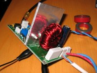
I think the distortion is now caused by the core material (Micrometals T157-40 .... I think .... fits with color coding and induction measurements) which is not very linear ..... though as I see it with only 16 V DC on the bridge, it is only "traveling" on a small and fairly linear art of the BH curve! .... But I guess it's enough to produce 1,7% 3. harmonic!
(still a bit shocked by how much the filter means in a class-d amp ..... and how little I understood coils, core materials, transformers etc. before I started this construction 😱 ..... think I'm begining to grasp a bit of the mystery 🙂)
I'm hopefully getting my T106-2 cores soon, and will see whether this makes a difference.
If not, the distortion comes from somewhere else 🙄
If I can get the distortion down to something like 0.1 - 1% with a PSU of something like 70 V DC running full power in 6 ohm I'll be satisfied, and will finish experimenting with this amp (It'll go into my subwoofer).
I'm thinking on starting a new amp based on a half bridge, which will make experimenting with the feedback circuit a lot easier (though there will probably be some other unforseen trouble instead 😉)
But well I have still got some work to do on this one before I'll move on (distortion still not fixed, and running on 70 V DC without blowing up 😀)
Will be starting on a protection circuit soon as well (DC, Imax, Heat)
My first intention was "of course" to make driver and fets a part of the self oscillating modulator, by taking the modulator feedback from AHSand BHS, but I couldn't make it work propperly, creating a true balanced modulator, so I decided to go for the circuit at hand.
The present feedback based around U1A/B is used to reduce distortion introduced by driver and fets. Changing the caps C1/C2 will not do much to lower the distortion in the audio band.
Actually I found a fault in the diagram, and therefore also in the circuit, as R3/R8 should have been 4k7 in stead of 47k and R2/R7 should have been 47k instead of 4k7!!!
This way I have already tryed changing the filter in the feedback chain from 3.4 kHz to 34 kHz. This had no influence on the distortion measured on a 1 kHz sine wave (would not understand if it did 😉) .... though it had some other positive effects, especially for "turn on" noise when the the whole circuit is stabilizing itself.
I think the distortion is now caused by the core material (Micrometals T157-40 .... I think .... fits with color coding and induction measurements) which is not very linear ..... though as I see it with only 16 V DC on the bridge, it is only "traveling" on a small and fairly linear art of the BH curve! .... But I guess it's enough to produce 1,7% 3. harmonic!
(still a bit shocked by how much the filter means in a class-d amp ..... and how little I understood coils, core materials, transformers etc. before I started this construction 😱 ..... think I'm begining to grasp a bit of the mystery 🙂)
I'm hopefully getting my T106-2 cores soon, and will see whether this makes a difference.
If not, the distortion comes from somewhere else 🙄
If I can get the distortion down to something like 0.1 - 1% with a PSU of something like 70 V DC running full power in 6 ohm I'll be satisfied, and will finish experimenting with this amp (It'll go into my subwoofer).
I'm thinking on starting a new amp based on a half bridge, which will make experimenting with the feedback circuit a lot easier (though there will probably be some other unforseen trouble instead 😉)
But well I have still got some work to do on this one before I'll move on (distortion still not fixed, and running on 70 V DC without blowing up 😀)
Will be starting on a protection circuit soon as well (DC, Imax, Heat)
You could try:
-to make a differential feedback.
-to make a dummy output filter with some resistors and capacitors and measure the distortion on this one to isolate the filter influence.
-to measure the drop over the coil with a scope to see if you are able to track the influence of the filter.
-to make a differential feedback.
-to make a dummy output filter with some resistors and capacitors and measure the distortion on this one to isolate the filter influence.
-to measure the drop over the coil with a scope to see if you are able to track the influence of the filter.
Hi Snickers
Measuring the voltage drop over the coil will just give me the modulated signal.
Think I'll try to make the dummy network, but I'm going on a business trip this week, so it'll have to wait 🙄
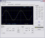
Not sure about my measurement setup either. I'm using a digital PC scope from Velleman, one chanel 12 MHz, which can also be used as a spectrum analyser.
But I have no extra filter on the input, so I'm not sure my measurements are actually correct.
Also just connecting the probe positive and it's ground, still produces a lot of spikes when moved near or connected to the amp GND = induced swhiching noise.
But measuring on a load and lowering the volume does lover the distortion to under the noise floor.
I think I need to have some better setup for destortion measurements 🙂
Measuring the voltage drop over the coil will just give me the modulated signal.
Think I'll try to make the dummy network, but I'm going on a business trip this week, so it'll have to wait 🙄
Not sure about my measurement setup either. I'm using a digital PC scope from Velleman, one chanel 12 MHz, which can also be used as a spectrum analyser.
But I have no extra filter on the input, so I'm not sure my measurements are actually correct.
Also just connecting the probe positive and it's ground, still produces a lot of spikes when moved near or connected to the amp GND = induced swhiching noise.
But measuring on a load and lowering the volume does lover the distortion to under the noise floor.
I think I need to have some better setup for destortion measurements 🙂
Measuring over the coil will probably give you a clue if the coil is a contributor to 3.harmonic distortion. But you may need to make a dummy parallell filter to compare it whith.
Got my new toroids today. Micrometals T130-2. Got room for 2 x 38 windings of d1,5 mm wire, which should correspond to 2 x 12 uH. Together with a capacitor of 1 uF, I should have a small peak at 18 kHz of +2 db and a -3 db point at 30 kHz, for a 8 ohm resistive load.
The 3. harmonic totally disappeared 😀
Now I only need to test that it doesn’t heat up when connected to a 56 V DC PSU, as the last coil.
Conclusion, Coils definitely does distort
(Not that that should be much of a surprise .... my surprise is more to the level it is distorting, if not constructed right, and the right materials are used!)
The fact that the 3. harmonic is surely only due to all even harmonics being canceled out in the balanced configuration, and I think you would see as much even order distortion in a single ended design.
There we go, that's one source for distortion ...... and one good reason to try out a post filter feedback design😉
That is good to hear!
If you connect the coil and measure the post and pre coil signals, and then connect the other coil and do the same again I think you will see what I ment by this measurement.
If you connect the coil and measure the post and pre coil signals, and then connect the other coil and do the same again I think you will see what I ment by this measurement.
Tried out the amp on 52 V DC (loaded voltage).
No heat at all from the coil 😀
Unfortunatly the switching frequency again dropped to under 100 kHz!
It turns out that the overall loop is actually determining the switching freq. After changing R4 to 45 kOhm it all rocks again 😀
On my small test speaker it plays really loud ... and I newer new that this speaker could play this loud and with such attack 🙂
Snickers: I still haven't tried your measurement. Not totally sure what you meant, but first measuring the spectrum after the coil, and then comparing it to a RC filtered signal after the output fets, seems as a good idea. Actually I have such a signal as input to the feedback differential amp (I could just measure over C1 or C2) and compare to the output after the filter.
But now I cnat just put in the old coil again as I had to cut the wire somewhat to get it out!
I guess there will not be much difference with the new coil, but thanks for the tip anyway 😉
Are you building on any amp yourself?
See picture of new coil
Attachments
Looks good, but are you sure the coil does not affect the switching frequency? Looks like an aweful lot of windings on such a small coil.
The fact that the switching frequency is lower may also cause a reduction to the 3. harmonic distortion. When you have the frequency up on its original value again you may also end up having the same 3. harmonic distortion again.
Yes, I am working on an amplifier myself, but it is not a traditional class D. It has a totally different layout compared to a class D.
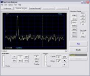
No visible 3. harmonic, see attached spectrum.
47.5 Vpp out in 4 ohm ..... damn I fried my littele test speaker in the proces of measuring this 🙁
🙁 
By changing R4 I'm back on 250 kHz, as I wrote in the last post.
The coil is a micrometals T106-2 RF coil, with a very low permeability (Al = 13.5 nH/N^2). It has 2 times 34 vindings of 1.5 mm wire. It's not that small 1" in diameter, but the rather thick wire takes up more room than anticipated. Maybe I could have done it with a thinner wire, but I'm not sure how to calculate the needed gauge!
Do tell a bit more about your amp 🙂 ..... sounds interesting.
47.5 Vpp out in 4 ohm ..... damn I fried my littele test speaker in the proces of measuring this
🙁 By changing R4 I'm back on 250 kHz, as I wrote in the last post.
The coil is a micrometals T106-2 RF coil, with a very low permeability (Al = 13.5 nH/N^2). It has 2 times 34 vindings of 1.5 mm wire. It's not that small 1" in diameter, but the rather thick wire takes up more room than anticipated. Maybe I could have done it with a thinner wire, but I'm not sure how to calculate the needed gauge!
Do tell a bit more about your amp 🙂 ..... sounds interesting.
Attachments
The goal of my amp is to gain bandwidth by overcoming the timing distortion problems. It also adds in some other advantages. So far it seems like I end up with somewhere around 300-400kHz of power bandwidth, but it is very early in the process and very difficult to say how it will turn out at the moment.
- Status
- Not open for further replies.
- Home
- Amplifiers
- Class D
- Distortion issues