Hi, i've build this tone control from the best italian magazine, Nuova Elettronica, i've build PCB by myself.
I really have a lot of distortion....😡
There is no problem of GND, OP amp amplifies and tone are ok, only distortion.
At this time i can't made a photo of board..
Can you help me?
I really have a lot of distortion....😡
There is no problem of GND, OP amp amplifies and tone are ok, only distortion.
At this time i can't made a photo of board..
Can you help me?
Attachments
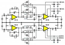
Nothing obviously amiss with the diagram.
Have you checked that each opamp output is at zero volts DC ? IC1B and IC2B rely on biasing via the bass control and a DC path back to IC1A and IC2A
Check those voltages first.
Beyond that and you probably need to use a scope and sine wave source and see what is going on.
Have you checked that each opamp output is at zero volts DC ? IC1B and IC2B rely on biasing via the bass control and a DC path back to IC1A and IC2A
Check those voltages first.
Beyond that and you probably need to use a scope and sine wave source and see what is going on.
Thank you. I used a 1mf electrolytic in input and output instead of polyester, but even if i use nothing, ther is always distortion.
Big problem is i haven't a scope... i can use the computer but it isn't the same thing.
Big problem is i haven't a scope... i can use the computer but it isn't the same thing.
Is the signal from the input buffer undistorted? Check simple stuff first.
Do you know that the circuit has been vetted with the values shown in the schematic? A lot of circuits on the web aren't. There's nothing wrong with the circuit shown (values would help a lot) and it is a very conventional configuration. But with tone controls, the two control circuits in the feedback path can interact and cause instability and distortion. It is convenient to separate both the turnover frequencies and the resistor/pot values by a decade to avoid this. Also make sure that the resistor values are high enough that they don't overload the op amps.
Sometimes moving one of the turnover frequencies a little clears up distortion.
Sometimes using a slightly larger shelving resistor can clear up issues. Also, use quality caps in the tone circuit, like film caps.
You can disconnect one network at a time and see if the issue clears up. This will point you in the right direction.
Of course, DC voltages have to all be correct first. It'll never work right if they're not.
Also, you need a coupling capacitor between the input stage and the tone control stage so the tone control stage has a DC gain of 1. If you do it right, the output offset should vary by no more than 25 mV when turning the bass control from one extreme to the other. Tone controls like this are not precision DC circuits, so coupling capacitors are a must. I always use these Aluminum Capacitors | Capacitors | DigiKey Nichicon "Muse" capacitors and I buy handy values (like 4.7 uF) in lots of 10 to save a little money.
Also, set a dominant bass pole at the input. This means that you will have to use a larger interstage coupling capacitor. The value of the interstage coupling capacitor is determined by the bass control circuit shelving resistor value; I recommend 10K minimum for this resistor.
Your op amp will have to drive the smallest value shelving resistor at high frequency without overloading. With a 5532 op amp I have found that 1K is a good minimum value for this resistor. Higher is better.
You now see that your op amp will have to have good drive current capability and decent slew rate. I recommend building your circuit to work with a 5532 (it's easiest) and then maybe swapping a different op amp in there. Whatever op amp you use will have to have good output current drive capacity and good slew rate.
Wow, thank you Eddie! I have no internet connection so i can reply later.. i'll made some photo. I'm using a LS4558 but only for test i've tried a bad TL082 too.
Now i study what you wrote..😉
Now i study what you wrote..😉
You're welcome.
Thevenin and Norton equivalent circuits, drawn for different frequencies (in your case low, mid, and high), will answer your questions. These simplified circuits will make it easy to see approximately what your circuit is doing. Then you have to deal with the real world scenario of interaction of the tone controls. This is where the rules of thumb come into play. Separating both resistor value regimes and turnover frequencies by a decade (at least if possible) is a great start.
I just got done with this process. I wanted to design a small tone control board that worked better than the usual controls you find. That's why it's so fresh in my mind.
Even better is to cascade the controls, but this throws another op amp into the mix for each control. But then they don't interact and you don't have to stagger resistor and frequency regimes by a decade. My circuit used small parts on a small board; that was my objective.
I've not used the pots in the board. I've solded each pin with a 20cm with a shielded cable, connecting all shields together to gnd, because i can not draw a dual layer pcb. Mybe this is yhe problem?
Shouldn't be a problem if your impedances aren't too high.
But if you make your boards small enough and use small pots, you don't have to do that. The fewer wires the better. My board fits in a small box with less than one inch total height available inside the box.
Did you power up and check DC voltages and signal trace? First things first.
What are your turnover frequencies anyway? To play it safe, you should use 100 Hz, 1 kHz, and 10 kHz. There is some wiggle room, and it's up to you to see what's up.
Last edited:
Hi, please remember English isn't my second language and Google can't translate correctly everything!
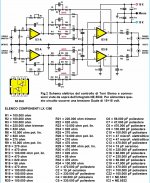
I've forget to post value of components, so this is the schematic complete.
It is important for you to know I've not studied electronics, i am only a hobbyst from more than 30 years.
I've known maybe the most important think is to check if there is a DC output, so i can test it very soon.
But before this, please check the values of components and tell me if maybe some problems with the cables
in the pots. Thank you my friens.
Attachments
Last edited:
Well, some of the shelving resistors are too low I think. This will increase distortion. Remember the 5532 is rated into a 600 ohm load. Higher will reduce distortion; in a circuit like this, 1K is a practical minimum value. And 10.000 = 10K I'm assuming. 10 ohms just won't work. And you still need a coupling cap between stages.
I didn't look at everything. Those errors jumped out at me right away. I don't think this circuit is properly vetted, at all.
Here's a better circuit. Hi-Fi Preamplifier I would still use input, interstage, and output capacitors.
I didn't look at everything. Those errors jumped out at me right away. I don't think this circuit is properly vetted, at all.
Here's a better circuit. Hi-Fi Preamplifier I would still use input, interstage, and output capacitors.
5532 op-amps can oscillate if there's no cap directly across pins 4 and 8. These caps should be X7R ceramic, around 100nF, and installed with very short leads to the power supply pins. Bypass caps to ground (as drawn) may not be adequate to insure stability with this chip, especially if hookup distance is significant.
Bypass caps to ground can also introduce noise into the ground.
The small bypass caps are supposed to provide local bypassing. Many op amp circuits don't actually have a ground. The signal they're processing is referenced to ground.
Plus experience says to put them right on the power lead pins.That's as local as it gets.
The small bypass caps are supposed to provide local bypassing. Many op amp circuits don't actually have a ground. The signal they're processing is referenced to ground.
Plus experience says to put them right on the power lead pins.That's as local as it gets.
Hi, my friends, due to some health problems, i've stopped experiments. I think i will mount another schematic totally different but i don't know when. Big thanks everybody for helping me!!!
Hi everybody! I've solved problem!!!
I've used a gain of 5 with a 470k resistor. Now I changed with a 100k, so gain is only 1.
Everything is ok! Now i have a little problem....i need more gain, what can i do?
I've used a gain of 5 with a 470k resistor. Now I changed with a 100k, so gain is only 1.
Everything is ok! Now i have a little problem....i need more gain, what can i do?
You need to show on the circuit exactly what you have done, but the obvious answer would be to use something between 100k and 470k.
I think he change R3 and R20 from 470k to 100k, so the gain is 1 (if set the variable resistor R4 and R21 to 0 Ohm).
So remain about 220k to increase the the gain up to 3 (220K+100k / 100k) .
So remain about 220k to increase the the gain up to 3 (220K+100k / 100k) .
Last edited:
Schematic in the first page...
i left only one resistor in feedback and removed trimmer, so gain is 1.
But if i increase gain, i get the distorsion, big distorsion...
i left only one resistor in feedback and removed trimmer, so gain is 1.
But if i increase gain, i get the distorsion, big distorsion...
- Status
- Not open for further replies.
- Home
- Source & Line
- Analog Line Level
- Distortion in a Tone Control