Interesting paper: https://core.ac.uk/download/pdf/11458689.pdf
Using multiple paths with phases shifts.
Anyone tried this with valves? (Yes I’m aware of the duplication)
Also: https://link.springer.com/content/pdf/bbm:978-94-009-5770-1/1.pdf
Using multiple paths with phases shifts.
Anyone tried this with valves? (Yes I’m aware of the duplication)
Also: https://link.springer.com/content/pdf/bbm:978-94-009-5770-1/1.pdf
Last edited:
There’s also this about parasitic cancellation in caps: (PDF) Cancellation of Capacitor Parasitic Parameters for Noise Reduction Application
I think I went on a high school study trip to Rome with the author 🙂
It can be done with tubes: every push-pull amplifier does it.
The paper shows the result of simulations in Matlab. I'm curious whether it works in real life with the tolerances of tubes. I guess you'll need matched pairs/quads/...
It can be done with tubes: every push-pull amplifier does it.
The paper shows the result of simulations in Matlab. I'm curious whether it works in real life with the tolerances of tubes. I guess you'll need matched pairs/quads/...
Wide band phase shifters require a large matrix like network of R-C sections. The wider the bandwidth, the larger the network. These networks are very lossy. (except for 180 deg. inverter) So more and more amplification will be required, with more and more distortion. Audio band.... worst case imaginable. This multi-path phase shift idea is a non starter.
That's not to say that some clever cancellation scheme can't be found. It obviously is easy to cancel even harmonics. So make everything an even harmonic:
Let x = +SQUARE(Signal), y = -SQUARE(Signal) .... 8 pages later, sum two phase split and P-P swapped/SQRT P-P then amplified components that add for signal and subtract for odd harmonics. Like (Q+R)^2 + (Q-R)^2 = [ Q^2 +2QR + R^2 ] + [Q^2 -2QR + R^2 ] = Q^2 + R^2 + Q^2 + R^2 = (amplified Signal)
The intermediate 8 math pages not immediately coming to mind. 😕😀
Simplest way I can think of is to use a constant gm (Crazy drive) amplifier output stage to avoid the main source of distortion in the first place.
Last edited:
Same as what is used for part of the modulator in Single Sideband (SSB) transmitters to get the 90 degree phase shift requitred. A large RC matrix. More BW needs more parts, gets a bit crazy.😱
For audio test tones, such as sinewave single frequency testing signals presented to a DUT, I have often used the signal generator in REW to add in harmonics such that the test signal being supplied to the DUT (whether that signal is the output of a non-ideal soundcard, or a subsequent booster amplifier) has all harmonics nulled to the available noise floor. The test signal being applied to the DUT is sensed by way of the REW spectrum analyser, and the harmonics are individually nulled down to the noise floor by visual inspection (and perseverance for how many harmonics one wants to null (up to 10th), and the bandwidth of the measurement system).
Last edited:
A Denon Technical Audio CD plus any CD player that is worth listening to, is a very low distortion signal source.
Sine waves (many frequencies), two tone 2nd and 3rd order Intermodulation tests, broadband impulse (for quick FFT frequency response testing), tone bursts, etc.
Example, set the CD player to Repeat 1 track, go to track # 18, and you have a low distortion 1kHz sine wave.
No low cost function generator can duplicate those tests.
Yes, a sound card can be very nice too.
Last edited:
CDs are limited to -96dB or so which is really not enough for today's high performance equipment.
A software generator through a good soundcard easily gets down to better than -120dB.
Jan
A software generator through a good soundcard easily gets down to better than -120dB.
Jan
I think extended dynamic range is most useful for doing mixing of multi-channel music recordings, so that we lose as little as possible when it is combined into such media as
[96dB] CDs.
Of course, with 0 dB as the threshold of hearing, and about 120 dB or so, being the threshold of one or the other of pain, drawing blood, or permanent damage to the ear, we might not need a power amplifier that has -120dBc spur-free, hum free, intermodulation free, and harmonic free distortions.
Just so we can be on an even playing field, lets connect our amplifier to an 8 Ohm non-inductive power resistor.
(never mind what a 25 foot speaker cable and loudspeaker load might do to amplifier distortions).
And how many of you have a listening room that is at 0dB, the threshold of hearing?
Or, have you ever measured the background sound level of your listening room?
How many loudspeakers have distortion levels that are -120dBc.
120dBc is a wonderful number, but I am not worried that my playback systems are orders of dB magnitude away from -120dBc.
Usually when I cook, I remove the outer layers of the Onion first.
The finer inner layers come after that.
I think there are several sound cards out there that are not spur free all the way to 120dBc, especially when it comes to spurs that are above 20kHz, but those spurs can potentially inter-modulate down into the audio band.
And forget about the problems of EMC when connecting a switcher powered computer, sound card, and an amplifier that are all plugged into the same power mains.
Pull the rug up, and see if anything is under it.
Last edited:
The advantage of laptops is that they are nearly a 'dime a dozen' and used by many school kids, and battery powered. And soundcard interfaces are USB powered from a laptop. That removes one or two earth loop headaches.
One benefit of having a low noise floor for testing is that DUT signals down at the -100 to -80dB level are very easy to discern, rather than trying to differentiate signal artefacts from a noise floor. The other benefit of using a test system that generates the test signal as well as analyses the DUT signal, is that advanced signal processing can further differentiate artefacts from the DUT noise floor using test frequency locking to the FFT conditions, and tracking/identification/plotting/reporting of the test frequency along with its harmonics and IM distortion components.
One benefit of having a low noise floor for testing is that DUT signals down at the -100 to -80dB level are very easy to discern, rather than trying to differentiate signal artefacts from a noise floor. The other benefit of using a test system that generates the test signal as well as analyses the DUT signal, is that advanced signal processing can further differentiate artefacts from the DUT noise floor using test frequency locking to the FFT conditions, and tracking/identification/plotting/reporting of the test frequency along with its harmonics and IM distortion components.
Last edited:
Part of a Paper on Wideband 90 Degree Phase Shifter
For anyone with the patience to build such a circuit. Found this a while back while looking for information on the simpler but meant for a similar application of the same thing as used in SSB Transmitters. This one is good out to 100 KHz. The SSB transmitter requires a phase shifter to cover only the voice band, nominally 300 to 3500 Hz & with limited dynamic range. As Smoking Amp has pointed out, that was done with an RC matrix. There is a description here somewhere in my pile but can't find it today. Lots more on the web tho.🙂
The rest of this paper gives RC component values for the OP Amps to make it work.
Attachments
One serious problem with any multi-path multi-phase amplifier scheme is that all the signal paths must have identical distortion properties. Now maybe an IC could get away with that, but using NOS tubes, NO WAY!
So I think the first principle must be to use a single amplifier path (could still be P-P or SE) and concentrate on linearizing that.
Ignoring classical N-FDBK, we still have some powerful tools. Distortion is just variance of gain. With a differential input stage, we can vary gain by varying the tail current. So a variable CCS gets used for the tail for compensating gain variation. Now we need a means to measure channel gain.
Suppose we inject a HF carrier freq. of small amplitude into the opposite side of the differential input stage, above the audible range.
At any operating point, determined by the actual input signal, increasing or decreasing the signal by some small delta (the HF carrier) will either cause no gain change, ideally, or an increase/decrease in gain (ie, indicating distortion). So the gain curve either is ramping up or ramping down if there is distortion present.
This would cause the HF carrier to increase in amplitude on one carrier polarity and decrease in amplitude on the other polarity. So distortion (or gain change) would cause generation of 2nd harmonic of the HF carrier. And a synchronous detector at twice the HF carrier (ie, at the 2nd harmonic) would produce a plus or minus output depending on the slope of the gain curve there. (this would be placed before the OT to avoid bandwidth problems) The HF carrier also has the effect of removing hysteresis from the OT as a side benefit.
Simplest solution is just to feed the synchronous detector output back to the variable CCS to maintain constant gain.
But we can do even better. A PID (proportional, integral, derivative) controller in that feedback can be used to predict the future variation of gain in the near interval (ie, following the input signal variation), and correct for it accurately.
This is the technique that was used to make the big breakthrough in class D amplifier quality. We can have a much faster loop here without the class D switching pulses getting in the way (or the OT).
Unlike conventional Neg. Fdbk, this scheme does not require high loop gain in the amplifier channel, just normal functional gain. So stability problems in the amplifier channel itself are largely avoided. Although a fast amplifier channel makes for less work for the derivative function in the PID controller.
I would hazard a guess that this could reach PPM distortion capability in tube amplifiers, just like SS amplifiers.
Of course, it never hurts to get rid of most of the inherent distortion in the amplifier channel right up front. Constant gm (Crazy drive) outputs could help greatly too.
@smokingamp - that’s what I was thinking, using 30khz signal which is close enough to be treated the same as audio too.
You can then use this as audio convolution estimation - like Astronomy when they use a laser to excite the atoms in the atmosphere and the. Look at the wavefront and correct using a flexible secondary mirror by inversing the wave front. The image is deconvolved so the image is clearer. I do the same with my astrophotography - using the stars as point spread functions to deconvolve the atmospheric and optical mess.
In this case the loadline distortion caused by nonlinearity then is corrected. A ccs would only vary the current. But non linearity of the waveform would still exist due the mathematical function still remains unchanged. As long as that is symmetrical then that’s good as you’d still get the A class tone.
Another though to get the noise of the tube is use a high V input op amp (250V inputs) one.
Another oddity and possibly heretical is this to use a high frequency digital pulse to multiplex two signals through the same valve. The audio waveform is almost like DC at this point vs the digital switching.
Now odds on that you may need to switch from audio valves to RF for noise and capability reasons.
Then the two signals are demultiplexed at the other end through a reconstruction filter. At a high enough digital rate you would then simply send the switching noise far up the spectrum without impacting the audio output.
The result is that you have an identical paths for two signals (stereo audio or distortion reference).
If two 180 phases for the same signal level are sent through (multiplexed so they don't cancel) for that voltage you have a differential - which gives you the distortion. Thinking about the load line and the non-linearity for Ug. Adjusting the valve could then result in a linear output (thinking pentode) just trying to think how that would be done triode style. Something to ponder.
Last edited:
A ccs would only vary the current. But non linearity of the waveform would still exist due the mathematical function still remains unchanged.
The varying tail current scheme is used often in SS for gain control and for multiply functions. The bipolar transistor gm is linearly proportional to current, so gain is controlled that way. (measured differentially, so that the current change itself does not produce an offset in that mode)
For tubes, the gm is proportional to SQRT(plate current), so this is still usable for gain control in a differential mode. And for a typical tube or Mosfet used as the variable CCS, Ip is prop. to Vg squared. So gain will be prop. to control Vg.
So overall amplifier gain is flattened out with the gain control type loop.
Using a PID controller in the loop then makes it predictive as well by following the rate of change.
There is a tube that already does the whole front end gain control -off the shelf- , the 6JH8 beam deflection tube. (which has a control grid for current control, and beam deflectors for linear differential signal gain) They are even cheap. Were used for SSB and TV chroma demod.
The main non-linearity in tube amps is the output stage. Crazy drive can give you constant gm there. (requires reduced idle current in class aB to avoid gm crossover doubling, which makes for efficiency as well) (perfect in SE mode too)
One -could- use a parallel bank of 6JH8 tubes for the output stage instead, but they are low power devices, would take a LOT of them.
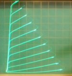
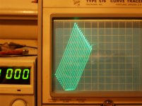
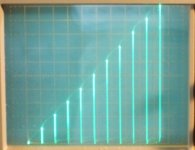
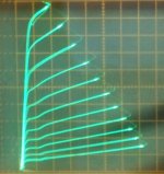
There is also the latest "new series Schade" (CED and UnSet at Tubelab) which can produce remarkably constant Mu triodes from cheap TV beam tubes. Sample curves below.
So one can start with an amplifier channel that is 1st order linear all the way thru, then apply the gain flattener loop to put the final finish on it. PPM distortion should be possible with attention to detail and power supply quality. That's not to say that any tubo-philes will like the sound of it though.
-----------------------------------------------------------------------------------------------------------------
The scheme of HF inverting the signal (then re-inverting) has been used to remove hysteresis from output transformers (OTs) using ferrite xfmrs. Check out the David Berning scheme. One has to clean up the switching transients with a filter.
Tubes are high bandwidth devices though, so even the HF inverting will still reveal the immediate gain distortion curve to the signal amplification.
A) Crazy drive (constant gm)
B) series Schade (CED,UnSet) (constant triode Mu)
Attachments

Last edited:
Oh yeah,
and one can also apply Crazy drive -AND- "new series Schade" (CED, UnSet) simultaneously to achieve the "WIRE with GAIN" device:
(takes a LOT of drive signal voltage however)
pic A) Wire with Gain (conventional Ip versus Vp plate curves with stepped Vg)
pic B) Ip versus Vg for Crazy drive
pic C) conventional grid 1 driven beam pentode curves for comparison. (what the tube amp world runs on)
pic D) Ip versus Vg for conventional grid 1 driven beam pentode
The Wire with Gain is interesting but not so practical.
Crazy drive is practical but has a high output Z by itself. A gain control loop (either conventional N Fdbk or the above gain controller loop scheme) will give Crazy drive a very low output Z.
Attachments

Last edited:
Been thinking about some other schemes to lower distortion unconventionally.
A very simple scheme is just to use an Op Amp to compare the input signal with an attenuated output signal from an existing amplifier, then driving the difference (error) into a ferrite toroid with the Op Amp. The main Amplifier secondary passing thru it once or twice. (so like one or two turns on it, and 100s of primary turns for the Op Amp to drive it) This is conventional feed-forward. The Op Amp just fixes the error in the Amplifier output. Just milli-Volts output to correct distortion, but does need high level current to match the amplifier level. Won't get you PPM level results, but should be fine for removing audible level distortions. Could be added onto most any tube Amp, maybe with a switch for enabling or disabling.
Then I began thinking about other clever add-ons.
One could monitor the output current of an existing amplifier while driving a speaker, and compare that current to the drive signal Voltage. Then a current output amplifier would be driven with the derived error and its current summed with the main Amplifier output, so as to make the load appear to be just a fixed resistor for that Amplifier. Maybe call it a load leveler. This would remove load variation and reactance from the main Amplifier, presumably improving its performance. (it is possible to parallel the outputs of a low Z Voltage amplifier and a high Z current amplifier without causing Amplifier indigestion)
Now once you have a load leveled Amplifier, there was a scheme mentioned a number of years ago, called Splif I think. This used two identical Amplifiers, one with a speaker load and the other with a fixed resistor load. The resistor loaded Amplifier had a conventional Neg. Fdbk network to remove distortion produced by the Amplifier. The same derived error N Fdbk signal was also fed to the other Amplifier (this time with a leveled speaker load). No N Fdbk loop is used in this Amplifier, just the error derived in the 1st Amplifier.
Assuming the Amplifiers are identical as far as distortion production, then both would be corrected to low distortion by the same error correction. The speaker loaded Amplifier, not having a Neg. Fdbk loop, would no longer have the "dreaded re-entrant N Fdbk distortion" producing higher harmonics.
The problem at that time was that a real speaker load would cause different distortion in that Amplifier compared to the resistor loaded Amplifier. But if the speaker loaded Amplifier has a load leveler circuit attached, then it would behave just the same as the resistor loaded Amplifier. In theory.... the scheme should now work. Of course getting two Amplifiers to have the same identical distortion would require some pretty darn good tube matching and pot tweaking.
But achieving this would be quite the novelty. A -NO- Neg. Fdbk Amplifier with low distortion. Well, this is one for the obsessive-compulsive types I think. But certainly interesting. My one issue with this scheme, assuming it could be achieved, is that the 1st Amplifier with the resistor load and Neg. Fdbk loop should be producing re-entrant loop distortion already. So one is just copying that over to the speaker loaded Amplifier. So maybe a futile approach. Gets the neurons firing anyway. Maybe some fix.
Last edited:
Addendum to the "Splif" dual Amplifiers scheme, one with resistor load and other with the speaker load (a leveled speaker now).
Maybe the resistor loaded Amplifier did NOT apply the derived error Fdbk to its input, so avoiding the re-entrant N Fdbk loop distortion effect. No need to actually fix the distortion there. Just supplying the error correction to be used by the other channel with the speaker (leveled speaker now). Good question what that actually does. A simulation would be ideal for resolving this. (just put identical resistor loads on both Amplifiers to test) One probably has to attenuate that error feedback signal difference some, since a real N Fdbk loop would reduce the output error and hence reduce the error feedback signal too.
One cold also flip the speaker leveling scheme around too. Measure the output current going to the real speaker and apply that correction (versus input V) to the resistor loaded amplifier via a current amplifier to duplicate the speaker loading there.
I think maybe the original Splif scheme ended up using two speakers, one hidden in a large sealed damped box to act as the dummy load, the other Amplifier/speaker actually active. Same idea basically.
Last edited:
- Home
- Amplifiers
- Tubes / Valves
- Distortion cancellation using phase shift