for high gain arrangements where the input signal is a tiny proportion of the supply rail voltage, the common mode distortion is usually extremely low. Other distortions usually dominate.
For a low gain arrangement where the input signal is a high proportion of the supply rail voltage, the common mode distortion can dominate.
In the context of high and low gain, low <3times (+10dB) and high is >5times (+14dB)
For a low gain arrangement where the input signal is a high proportion of the supply rail voltage, the common mode distortion can dominate.
In the context of high and low gain, low <3times (+10dB) and high is >5times (+14dB)
In the context of high and low gain, low <3times (+10dB) and high is >5times (+14dB)
When you talk about gain, do you imply close loop gain, or simple the signal level? I would imagine this distortion won't easily be fixed by open loop gain, since it occurs at input stage.
But that's very good information, thank you.
They were referring to closed loop gain. JLH addressed this way back last century.
Take an opamp used as a follower where the open loop gain is 100000times and the closed loop gain is 1times. The distortion should be virtually zero, but as pointed out by many the common mode distortion becomes high when the signal passing through approaches the supply rails. Assuming that opamp were on +-9Vdc supplies then when a 4Vac passes through the signal peaks are ~ 63% of the supply voltage. The common mode distortions will be higher.
Now compare to an opamp (or power amplifier) with a closed loop gain set to 20times.
The input signal (for the same 4Vac output) is now only 3% of the supplies. That reduces the common mode distortion.
Low closed loop gain amplifiers do benefit from the reduced common mode distortions given by inverting topology.
High gain amplifiers do not need that benefit and in return give improved noise performance.
Loud and clear Sir. I forget to see the problem from input voltage level, silly me. Thank you for explaining it so well.
Referenced in my own article!For those that are interested in common-mode distortion in JFET-input op amps, and why it is dependent on source impedance for some op amps, I've written an article on this topic: http://www.ti.com/lit/an/slyt595/slyt595.pdf
Input Protection for Low-Distortion Op-Amp Circuits | Electronic Design

Referenced in my own article!
Input Protection for Low-Distortion Op-Amp Circuits | Electronic Design
Great article! I enjoyed reading it!
I recently learned that there is a discussion here about common mode input distortion of J-FET input op amps.
I have been interested in this distortion for a long time and have been collecting data.
Below is the data I took in 2010.


Of these, OPA827 shows the worst characteristics.
I thought the reason was as follows.
1. OPA827 omits the cascode bootstrap that OPA627 had.
2. OPA827 has excellent noise characteristics (4nV / √Hz) as a FET input OP-Amp, so FET with a large gm is used in the input stage, which increases the junction capacitance.
3. J-FETs that do not seem to directly contribute to the gm of the first stage are connected in parallel.(This FET seems to be working to get the output from the source side)
So I was surprised to see the data attached by johnc124 in # 34. Both OPA827 and OPA1641 show incredibly low distortion. It's too far from the data I got. I thought there would be something wrong with Mr. johnc124's measurement.
So I took this data again under the same conditions as johnc124 and Samuel Groner's instructions
However, my measurement system (self-made) is a 20, 100, 1k, 6.3k, 10k, 20kHz 6-point spot oscillator and distortion meter composed of a notch filter (twin T) tuned to that oscillator. With 100kHz LPF.
The data is shown below. (The s after the model number is ssop) The input levels are 18dBu (6.16Vrms) and 20dBu (7.75Vrms).


First of all when I ordered the OPA827 from Digi-Key about 5 years ago, I had the one that I bought the SSOP by mistake it's suffix, so I measured it. Also, about two years ago, I bought a single type OPA1641 (SOP) and a high-precision OPA140 (SSOP), so I measured them.
Surprisingly, they have very low distortion. (Lower three curves)
Fortunately, I still had the both OPA827 (SOP) and OPA1642 (SOP) that measured in 2010 so when I measure them (Upper two curves), the distortion is still large, reaching 100 times that of the new one.
This may be due to the old being fake or damaged.
But,
OPA1642 was provided as a sample by a sales representative of TI Japan's Osaka sales office. (At that time, I was working for an electronic device manufacturer in Kansai) There are four samples, but all eight units have similar characteristics, although there are some individual differences.
And,
OPA827 was purchased at a major electronic parts retailer in Nipponbashi, Osaka, and I think it was purchased through an authorized distributor. Both of the two purchased at that time show similar characteristics.
And best of all, Samuel Groner's "Operational Amplifier Distortion"
https://www.nanovolt.ch/resources/ic_opamps/pdf/opamp_distortion.pdf
(375p middle left, green curve) is very similar to the data I took.
I don't think it matters here whether the package is SOP or SSOP, single or dual. Even if there is a slight difference in characteristics due to heat generation, it should not be so different.
The problem is that they are products immediately after release, I come to the conclusion that these two varieties only can be considered to have undergone design changes after their release.
johnc124 may not be able to answer accurately because it may conflict with corporate secrets.
The latest data sheet of OPA1642 has added a graph of common mode voltage vs. input capacitance called "Extremely Stable Input Capacitance", but the old data sheet (REVISED APRIL 2010) I saved does not have that graph.
Samuel Groner made no comments on johnc124's data, but he must have been as surprised as I was.
He doesn't seem to have visited here lately, but if you're looking here, I highly recommend getting a new OPA827 and measuring it.
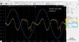
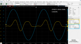
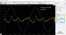
The distortion waveforms of the old and new OPA827, the old OPA1642 and the new OPA1641 are attached. They are at 1kHz 20dB and 20kHz 20dBu, respectively.
The range on the vertical axis is not the correct value because it is the waveform of the monitor output of the distortion meter.
The cyan waveform should be read as 2.5V/div in the input waveform to the distortion meter.
The yellow waveform is a distortion component and has been adjusted to a size that is easy to see.
P.S.
The only reason I think there is such a dramatic improvement is the addition of the Cascode bootstrap to the input stage.
I thought that If so, isn't the common mode input range on the high side narrowed by the cascode?
Therefore, I compared the levels at which the input signal was gradually increased and the distortion increased sharply, but no significant difference was found between the old and new op-amp
I have been interested in this distortion for a long time and have been collecting data.
Below is the data I took in 2010.
Of these, OPA827 shows the worst characteristics.
I thought the reason was as follows.
1. OPA827 omits the cascode bootstrap that OPA627 had.
2. OPA827 has excellent noise characteristics (4nV / √Hz) as a FET input OP-Amp, so FET with a large gm is used in the input stage, which increases the junction capacitance.
3. J-FETs that do not seem to directly contribute to the gm of the first stage are connected in parallel.(This FET seems to be working to get the output from the source side)
So I was surprised to see the data attached by johnc124 in # 34. Both OPA827 and OPA1641 show incredibly low distortion. It's too far from the data I got. I thought there would be something wrong with Mr. johnc124's measurement.
So I took this data again under the same conditions as johnc124 and Samuel Groner's instructions
However, my measurement system (self-made) is a 20, 100, 1k, 6.3k, 10k, 20kHz 6-point spot oscillator and distortion meter composed of a notch filter (twin T) tuned to that oscillator. With 100kHz LPF.
The data is shown below. (The s after the model number is ssop) The input levels are 18dBu (6.16Vrms) and 20dBu (7.75Vrms).
First of all when I ordered the OPA827 from Digi-Key about 5 years ago, I had the one that I bought the SSOP by mistake it's suffix, so I measured it. Also, about two years ago, I bought a single type OPA1641 (SOP) and a high-precision OPA140 (SSOP), so I measured them.
Surprisingly, they have very low distortion. (Lower three curves)
Fortunately, I still had the both OPA827 (SOP) and OPA1642 (SOP) that measured in 2010 so when I measure them (Upper two curves), the distortion is still large, reaching 100 times that of the new one.
This may be due to the old being fake or damaged.
But,
OPA1642 was provided as a sample by a sales representative of TI Japan's Osaka sales office. (At that time, I was working for an electronic device manufacturer in Kansai) There are four samples, but all eight units have similar characteristics, although there are some individual differences.
And,
OPA827 was purchased at a major electronic parts retailer in Nipponbashi, Osaka, and I think it was purchased through an authorized distributor. Both of the two purchased at that time show similar characteristics.
And best of all, Samuel Groner's "Operational Amplifier Distortion"
https://www.nanovolt.ch/resources/ic_opamps/pdf/opamp_distortion.pdf
(375p middle left, green curve) is very similar to the data I took.
I don't think it matters here whether the package is SOP or SSOP, single or dual. Even if there is a slight difference in characteristics due to heat generation, it should not be so different.
The problem is that they are products immediately after release, I come to the conclusion that these two varieties only can be considered to have undergone design changes after their release.
johnc124 may not be able to answer accurately because it may conflict with corporate secrets.
The latest data sheet of OPA1642 has added a graph of common mode voltage vs. input capacitance called "Extremely Stable Input Capacitance", but the old data sheet (REVISED APRIL 2010) I saved does not have that graph.
Samuel Groner made no comments on johnc124's data, but he must have been as surprised as I was.
He doesn't seem to have visited here lately, but if you're looking here, I highly recommend getting a new OPA827 and measuring it.
The distortion waveforms of the old and new OPA827, the old OPA1642 and the new OPA1641 are attached. They are at 1kHz 20dB and 20kHz 20dBu, respectively.
The range on the vertical axis is not the correct value because it is the waveform of the monitor output of the distortion meter.
The cyan waveform should be read as 2.5V/div in the input waveform to the distortion meter.
The yellow waveform is a distortion component and has been adjusted to a size that is easy to see.
P.S.
The only reason I think there is such a dramatic improvement is the addition of the Cascode bootstrap to the input stage.
I thought that If so, isn't the common mode input range on the high side narrowed by the cascode?
Therefore, I compared the levels at which the input signal was gradually increased and the distortion increased sharply, but no significant difference was found between the old and new op-amp
Attachments
-
 OPA827_20dBu_1kHz.png34 KB · Views: 249
 -
 OPA827_20dBu_20kHz.png34.8 KB · Views: 252
 -
 OPA827s_20dBu_1kHz.png36.8 KB · Views: 247
 -
 OPA827s_20dBu_20kHz.png33.6 KB · Views: 241
 -
 OPA1642_20dBu_1kHz.png32.9 KB · Views: 236
 -
 OPA1642_20dBu_20kHz.png33.6 KB · Views: 233
 -
 OPA1641_20dBu_1kHz.png35.7 KB · Views: 240
 -
 OPA1641_20dBu_20kHz.png33.3 KB · Views: 271
Your data reflects a change made to the process technology around the 2010 timeframe. In it's original form, the process that the OPA827 and OPA164x devices are fabricated on was not a fully dielectrically isolated technology. We were not happy with many aspects of the amplifier's performance and changed the process to fully isolate the transistors from each other. The results in vastly improved common mode distortion (among other specs). It's really cool to see this in your data, I had thought about illustrating this for customers at some point, because many still have a negative view of those devices due to their original incarnation. Obviously, the OPA827 today is NOT the OPA827 of 2010.
That's excellent data, Mason, thanks for sharing it. I agree with John that it's really cool to see the effect of the process change, and especially from an independent source.
Thankyou Rco3.
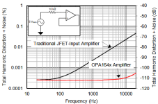
Here is a graph showing how good the reincarnation of OPA827 and OPA1641 is.
(One C-MOS is included. OPA604 is almost the same as OPA2134, so it overlaps.)

"OPA828 is slightly inferior to them."
"OPA1656 is a bit inferior due to CMOS protection, but it's not bad at all."
"Analog Devices's are more expensive but inferior"
Everything is exactly what John says!
Here is a graph showing how good the reincarnation of OPA827 and OPA1641 is.
(One C-MOS is included. OPA604 is almost the same as OPA2134, so it overlaps.)
"OPA828 is slightly inferior to them."
"OPA1656 is a bit inferior due to CMOS protection, but it's not bad at all."
"Analog Devices's are more expensive but inferior"
Everything is exactly what John says!
I have a silly question again but hope that John can give some advice.
There is a whole new collection of JFET (single) opamps from TI today :
OPA1642, OPA140, 141, 145, .... in addition to the old faithful OPA132, 134, 627, ....
I want to use one for a DC servo application.
Say down to 1k load, supply voltage 6~12V, output to 1V from both rails.
How should I choose ?
Oh, the power supply has a slow ram of about 1s.
Any way I can avoid huge DC at the opamp output during start up ?
Many thanks in advance,
Patrick
Hi folks,
i just found this old thread and i'm confused:
According to the OPA1642 datasheet the noise performance of this jfet amplifier should be better than OPA1612 as soon as the source resistances becomes > 3KOhm.
And the input capacitance of this OpAmp should be constant.
But the measurements above suggests that a jfet OpAmp (with the exception of OPA627) degrade the THD+N performance dramatically in every common-mode application. An impedance matching for the (+) (-) inputs would probably improve the situation.
-> Can we now conclude that it its generally a bad idea to use a jfet OpAmp as buffer or for + amplification [if source reistance can vary and no +/- impedance matching is possible] and it should only be used for inverting amplification?
Last edited:
It strongly depends on source output impedance. As it is usually <= 200 ohm from DACs or CD players, it does not matter much. Going to inverting scheme eliminates CM distortion, however the resistors have to be kept low for noise reasons, which leads to low input impedance. So there is no free lunch and no simple answer. Just do it right in the right circuit.
Do ”the measurements” refer to my measurements in posts #48 and 52?
If so, there is no discrepancy. It is just that the measurement conditions are very different from TI's.
My measurements have a signal source impedance of 100kΩ and an input signal of 7.75Vrms.
This is according to Samuel Groner's instructions.
He measured under much harsher conditions in order to make a big difference due to the OP-AMP.
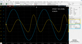
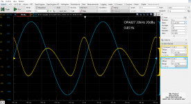
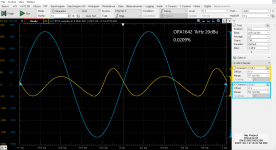
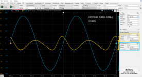
The following is a comparison of the same OPA1641 with f = 10 kHz, G = +1 (Rf = 0 Ω) and Vs = ±15 V.
The scope range was kept the same for easy comparison.
If so, there is no discrepancy. It is just that the measurement conditions are very different from TI's.
My measurements have a signal source impedance of 100kΩ and an input signal of 7.75Vrms.
This is according to Samuel Groner's instructions.
He measured under much harsher conditions in order to make a big difference due to the OP-AMP.
The following is a comparison of the same OPA1641 with f = 10 kHz, G = +1 (Rf = 0 Ω) and Vs = ±15 V.
The scope range was kept the same for easy comparison.
| Vin=5Vrms, Rs=10kΩ, (TI's measurement condition) THD+N=0,00027% | Vin=7.75Vrms, Rs=100kΩ, (my measurement condition) THD+N=0,0028% |
- Home
- Source & Line
- Analog Line Level
- Distortion and Source Impedance in JFET Input Op Amps