Hi!
I found this Distortion Analyzer circuit diy project.
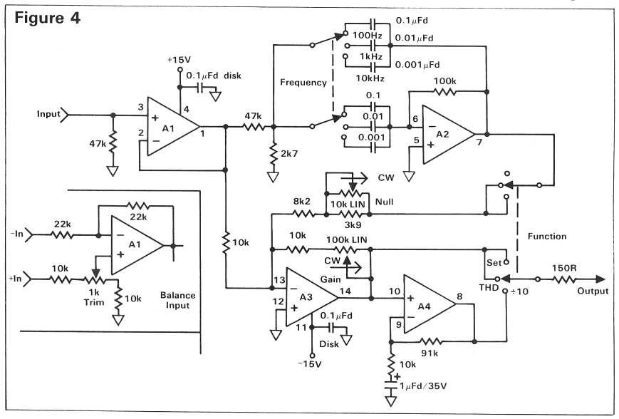
You will need 4 op-amps (2 dual).
Wouldnt it be nice to be able to checkout
if your amplifier show more or less distortion, after you have modified it.
1.0 Volt AC at output means 1.0% distortion.
Note, you will need a good multimeter, which can measure AC-voltage at frequencies above 400 Hz.
Article:
http://www.ethanwiner.com/distort.html
Circuit:
I found this Distortion Analyzer circuit diy project.
You will need 4 op-amps (2 dual).
Wouldnt it be nice to be able to checkout
if your amplifier show more or less distortion, after you have modified it.
1.0 Volt AC at output means 1.0% distortion.
Note, you will need a good multimeter, which can measure AC-voltage at frequencies above 400 Hz.
Article:
http://www.ethanwiner.com/distort.html
Build a Tape Linearizer and a Distortion Analyzer
by Ethan Winer
This article first appeared in the December 1981 issue of Recording-engineer/producer magazine.
SETUP AND USE
Once you've completed building the unit, plug it in, turn it on, and pray it doesn't blow up! If it passes the smoke test,
take a voltmeter and check each op-amp's output pin - these are conveniently located in the corners of the IC. The DC
voltage should be within a few millivolts of ground; if it is not check your wiring and/or try another IC. Now you are
ready to begin measuring distortion. The first thing to measure should be your sine wave oscillator, so connect it to the
analyzer's input.
Start with the output frequency set to 1 KHz., the function selector to Set, the null pot in the middle, and the analyzer's
gain control at minimum. Now adjust the oscillator to some reasonable output level, and increase the analyzer's gain
control until its output reads 10 volts on an AC meter. (Note that many digital multi-meters do not have a frequency
response that extends beyond a few KHz., so an analog meter is a better choice. Also, since the test procedure involves
nulling, a mechanical meter is much easier to interpret.)
With the full-scale set at 10 volts, switch the function selector to THD, and alternately adjust the null pot and the
oscillator's frequency to obtain the minimum reading possible. Now select the Divide by 10 switch setting and continue
tweaking until you are satisfied that you have completely canceled the 1 KHz. fundamental tone. You are now reading
distortion directly in percent - that is, 10 volts equals 10%, 0.1 volt equals 0.1%, and so on. You will probably find that
due to capacitor tolerances, the 1 KHz. setting is not precisely 1,000 Hz. Again, it doesn't really matter, but you should
make note of the actual frequency to save time in the future. Try the same thing at 100 Hz. and at 10 KHz. (or whatever you
choose), and you'll be an old pro in no time at all.
Circuit:
It's easier to use a pc soundcard these days
Wavetools (freeware) includes a spectrum analyser
http://www.sonicspot.com/wavetools/wavetools.html
Wavetools (freeware) includes a spectrum analyser
http://www.sonicspot.com/wavetools/wavetools.html

in power amplifier reviews from Stereophile there are show diagrams with the distortion wave form (fundamental notched out) - check out post #2 under
https://www.diyaudio.com/community/...st-possible-thd-n-really-the-best-way.367692/
for any examples.
Are there an easy to realize diy project to create such diagrams (e. g. for compare different integrated operational amps) ?
https://www.diyaudio.com/community/...st-possible-thd-n-really-the-best-way.367692/
for any examples.
Are there an easy to realize diy project to create such diagrams (e. g. for compare different integrated operational amps) ?
The Bob Cordell analyzer is a classic and good to 0.0002% midband. http://www.cordellaudio.com/papers/build_a_thd_analyzer.shtml
Sound card is the easiest thing these days. My only complaint is verifying what it tells you without a hardware analyzer.
I've messed with some of the very simple circuits and never had great success, but the one above looks like it should work. Remember, you need a low THD source to go with it. IMO, looking at the residual on a scope is way more useful than a raw number.