Hi,
I would like to open the discussion about a surprising subject I discovered during some distortion analysis with PSpice.
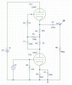
The initial intention was to investigate the behaviour of the intermediate resistor during distortion analysis. At first, we have a mu follower circuit with 12ax7 and a coupling capacitor at the lower stage. (see attached file).
...
I would like to open the discussion about a surprising subject I discovered during some distortion analysis with PSpice.
The initial intention was to investigate the behaviour of the intermediate resistor during distortion analysis. At first, we have a mu follower circuit with 12ax7 and a coupling capacitor at the lower stage. (see attached file).
...
Attachments
There is nothing surprising with the distortion of the u-Follower into different loads. John Broskie has described it on his page
www.tubecad.com. Look at the SRPP articles.
Reinhard
www.tubecad.com. Look at the SRPP articles.
Reinhard
Although that circuit is technically a mu-follower, there's hardly any resistance for the upper valve to bootstrap, so the lower valve will see a load of only a couple of hundred k. To gain the advantage of mu-follower action that 2k resistor really ought to be more like 22k or 47k so that the lower valve sees a load resistance much larger than its anode resistance.
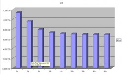
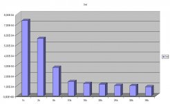

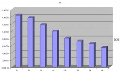
If we investigate the numbers, the mu follower without coupling capacitor provides lower absolut distortion values and we have an optimal intermediate resistor because of the second order minimum.
docali said:If we investigate the numbers, the mu follower without coupling capacitor provides lower absolut distortion values and we have an optimal intermediate resistor because of the second order minimum.
Interesting indeed, but what was the gain and the output level and do you investigate with heavier loads ?
Say 100K or 200K, more practical values for the grid leak of the following stage.
Yves.
Hi,
input voltage was 5mV in order to resemble a phono cartridge. Output level is nearly 500mV or less because the mu of 12ax7 is 100 and the mu follower has an amplification of nearly 100, decreasing with decreasing intermediate resistor.
Changing the load resistor to smaller values is a good idea! I will test it...
Docali, you really should try substantially increasing R5 (and the HT voltage to suit). As a rule of thumb, R5 should drop about 100V.
As it happens, I was testing some 6SL7 today with an active load (similar to a good mu-follower) and typically measured about 0.15% 2nd harmonic at an output level of 14VRMS. All other harmonics were better than 20dB down on the 2nd. Since distortion is proportional to level, I would expect 0.005% 2nd harmonic to be achieved at your test level of 500mVRMS.
As it happens, I was testing some 6SL7 today with an active load (similar to a good mu-follower) and typically measured about 0.15% 2nd harmonic at an output level of 14VRMS. All other harmonics were better than 20dB down on the 2nd. Since distortion is proportional to level, I would expect 0.005% 2nd harmonic to be achieved at your test level of 500mVRMS.
Ok, some variations for the mu follower without coupling capacitor:
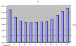
First, I lowered the load resistor R4 to 100k as proposed and I tried larger intermediate resistor R6. It should be mentioned that for every load resistor the voltage was atjusted to give nearly the same current and the only difference is the voltage to be dropped across the intermediate resistor. This procedure was also used for all previous investigations.
But the result is the same. The second order distortion undergoes a minimum.
What could we learn from this? The mu follower with coupling capacitor with respect to distortion should have an intermediate resistor as large as possible but if we remove the coupling capacitor of the lower stage things change and we have an optimal area of intermediate resistors with respect to second order distortion.
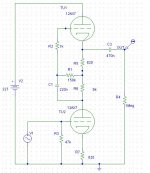
Attachments
- Status
- Not open for further replies.
- Home
- Amplifiers
- Tubes / Valves
- Distortion analysis mu follower