is there a certain distance that the light has to be from the fresnels. i am using the fresnels from a ohp. they are split.
Shouldn't it be the focal distance of the fresnel?
As I understand it, the purpose of the first fresnel is to make the radial light coming from the light source into parallel light going through the LCD.
Therefore, the light source should be at the focal point of parallel light going the opposite direction.
Similarly, the projection lens should be very near the focal point of the second fresnel in order to capture as much as possible of the light that has come through the LCD panel and project it onto the screen.
What I'm not so sure of is this: If you have a parabolic reflector, do you need the first fresnel lens at all, since you should have a (mostly) parallel light source to begin with?
suggestions
If you have a parabolic reflector that has a slightly wider diameter then the LCD, and is being used correctly, then you don't need the condensor fresnel. You still need the field fresnel to converge that parallel light into the projector lens.
You can measure the focal length of individual (ie split) fresnels just like you measure it for any other lens: Take it out at midday, and face the rough side to the sun. Move the lens down toward the ground until you get the smallest possible image of the sun. Measure the distance from the lens to the image spot on the ground. Try not to set anything on fire!
Put the condensor fresnel at it's focal length from the lamp arc to start. Then once you see where the projector lens has to go to get your screen image focussed, you can adjust the lamp arc to fresnel distance a bit to get the image of the lamp arc focussed into your projection lens. You should not have to move the condesnor fresnel more than a centimeter or two. If that doesn't get it, then you may have to put the field fresnel on the other side of the LCD to get the arc image into the lens.
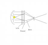
I'm wondering. If a parabolic reflector is used, will not the light that comes directly from the light source (without beeing reflected) cause errors? That light will not come in parallel to the other light that comes through the lcd and the fresnel, and thus the light going through a specific lcd pixel will be placed in different parts of the final image.
I'v attached an image that hopefully will make you see what I mean.
Using a reflector in front of the light source so that only reflected light will come to the lcd would make a dark spot in the center of the image where the reflector prevents the light to pass. Placing the light source a little bit farhter away from the parabolig reflector would "fix" this, but then the light that comes to the lcd won't be parallell.
And also, doesn't this problem exist in most setups that uses reflectors?
Attachments
reflector issues
Yes, using a parabolic reflector with an unshielded lamp will give you a lot of direct light that may cause a fuzzy image. (Most of that light will not even end up at the projection lens.) But you can add a tiny spherical reflector to send the useless light back through the lamp arc to the parabolic reflector. Lots of commercial projector lamps have such a tiny reflector built into the lamp. It would make a hole in the center of the light, except for the fact that the arcs of the lamps we use are so big that the light is never really all going in parallel.
Spherical and elliptical reflectors don't have this problem when they are used correctly. But still do have the problems associated with the large lamp arc. A really good projector lens will focus all the different rays passing through a pixel to a single point on the screen. A bad projector lens will send them to slightly different parts of the screen to give you a blurry image. You can get a good image with a small lamp arc or a good lens. If you have neither one of these, you will not be happy with the image.
How large is an arc that is too large to be useful?
Anything over 5mm. I wouldnt say useful, efficent is a better word.
Trev🙂
good lens with long arc?
>How can a lens compensate for the size of the lamp arc?
If the arc length was 0 mm, then you would not even need a projection lens: Every pixel on the LCD would be lit by a ray from a single direction. The condenser system would direct that ray to one point on the screen. In effect, this would be like using a pinhole lens. Or without a condenser system, the light would form a perfect image at any screen distance just by simple projection of the rays. With a condensor system and a projection lens, the ray from each pixel would strike only a single point on the lens so the lens would not have to focus anything. The screen image might be distorted by different refractive bending by different parts of the lens, but all of the light through an LCD pixel would end up at a single point on the screen. Even with a very bad lens, you would get a sharp image.
If the arc length is very small, (ie. 1mm), then the cone of rays passing through a single pixel will strike a very small area of the projection lens. The amount of aberration and distortion over that small area will be very low, even in a bad lens. So the rays will be focussed well on a very small area of the screen.
If the arc length is long, (ie. 24 mm), then the cone of rays passing through a single pixel will strike most of the lens. If it is a bad lens, then the result will be light scattered all around the desired pixel position on the screen because all of the lense's aberrations and distortion will affect it. If it is a good lens, then the rays will all be focussed to one point on the screen.
If the arc length was 0 mm, then you would not even need a projection lens:
Thats right cos we wouldnt even have a light lol, sorry had to say it.😀
Im kinda lost in what your saying guy cos we dont focus to the light, we focus to the image plane, we project it, it has nothing to do with arc size. Distortion does.
Trev🙂
let's try again
Maybe an analogy from photography will help:
If you take a photograph with your lens iris wide open, then you get very little depth of field. If you have a good lens, then you can still get a decent picture. If you have a bad lens, then it will be blurry.
If you close down the lens iris, then you get much more depth of field. Then even a bad lens (even a lens without a focus adjustment) will give you a sharp image.
The arc length has the exact same effect as the iris diameter in a camera: With a long arc you are using more of the surface area of the projection lens to form each pixel on the screen. So all of the aberrations or distortion present in that large area of the projection lens will show up in the screen image.
Thats right but i dont get how you say we dont need a projection lens cos we do if we want to have the image magnified on the wall, thats what i was going on about. If you had your light rays perfect and if you wanted your image the same size as the image plane you wouldnt need a projection lens no, but i think both you and i know in a real world environment thats not overly possible and not what we are doing here.
I get what your saying about the iris, not only do they cut light but also give a narrow feild of veiw when closed, slightly different to what we do but i get your example.
Trev🙂
I get what your saying about the iris, not only do they cut light but also give a narrow feild of veiw when closed, slightly different to what we do but i get your example.
Trev🙂
point-source light
In the first example, I was talking about a point-source light, which doesn't really exist! But the sun is a pretty small angle light source. If you have the sun shining through a stained glass window, then the image of the window will be projected onto the floor or the walls. it won't be sharp because the sun is not a point source, but it will be an image.
You can duplicate the same effect by taking a transparency outside. I have a test transparency sheet mounted in a frame with some fine lines and text printed on it. If I hold it a few inches from a white surface with the sunlight going through it, I can read the text and see the fine lines on the surface. This is projection without a lens. If I move it further away from the surface, it gets more dispersed but I can still see the fine lines. This is like having a small arc lamp. If I had a better point source light, then there would be less dispersion and I could move it further away and still be able to read it.
If I did this on a cloudy day, the shadows would be so fuzzy that I would not be able to see the fine lines at all on the white surface. This is like a large arc.
Just to see what happens with a smaller arc lamp, I took my transparency outside again with a -500 mm fl PCV lens. Without the lens, I can still read the projected text on the white surface with a projection distance of about 4 inches. If I hold the negative lens between the sun and the transparency, then I can move the transparency out to about 12 inches and still read the tiny text. The negative lens makes the sun look smaller, just like using a smaller arc length lamp.
If I did this on a cloudy day, the shadows would be so fuzzy that I would not be able to see the fine lines at all on the white surface. This is like a large arc.
Diffused/scatterd light, different from having a large arc but simillar effect. Its only on the edges of the image with a large arced lamp not the center..
If you have the sun shining through a stained glass window, then the image of the window will be projected onto the floor or the walls. it won't be sharp because the sun is not a point source, but it will be an image.
Paralelle light, well more so paralelle considering the suns distance. You can do this with a decent parabolic reflector providing its 0deg.
If you have an arc thats 1mm on all axis you have a point source, well, close enough. A point source is realy only a mathimatical reference point.
Trev🙂
15 feet?
I also have a question. Please let me know if this isn't the right spot for it.
In an earlier post on Hezz's "Assault on high end" thread (http://www.diyaudio.com/forums/showthread.php?s=&threadid=46807), Guy explained
>I think you might want to think about a design that uses an elliptical reflector with a positive lens just past the focal point to make a small parallel beam. Then you can use a polarized reflector to send the incorrectly polarized light to another path for re-orientation. Then add it back to the main path with a beam splitter prism. Then a lens could spread it to a fresnel for the LCD.
I'm wondering, how tightly could this parallel beam be collimated? Would it be practical to shoot it a distance of say, 15 feet, before the second lens (spreading it to the first fresnel)?
I'm excited about the idea of polarization recycling, and thought it might also be cool to have the light box separate from the LCD box (for noise, heat and bulk reasons). The idea of being able to usefully place beamsplitters and mirrors around my living room, optics-lab style, is for some reason very appealing.
Pipe dream? Too much light loss?
By the way, as a long time reader but new poster, I'd like to give huge thanks to Guy, Ace, and all the other very talented & helpful people on this forum. I've had a great time reading about all the cool ideas going into (& coming out of) these amazing projects people are building!
Charlie
1600sw, SGI O2
nice drawing
Looks very nice, but I think it is very difficult to collimate a beam to go 15 feet without spreading. You need some very precise aspherical optics designed just for your setup. It would also probably have to use a dual-slit device to remove non-parallel rays. That works by just throwing away the light that is not going in the right direction. With the typical lamp arc lengths in the bulbs we use, you could never do it.
Maybe you could satisfy your need for nifty optical displays by adding some laser beams bouncing off mirrors in your media room? They could do something useful, like serving as aisle indicators, etc. They do tend to be collimated very well, since it is far easier with monochromatic light coming from a very small point source.
And you are quite welcome! It has been a lot of fun reading, trying, and posting all these different ideas. Keeps my brain alive!
light pipe
Thanks very much for your response Guy. I wouldn't want to remove 80% of the light just to make the lightbox a little more distant... better off just using a 80% smaller (quieter cooler lighter) bulb in the LCD box!
It's great to get these things answered before spending a bunch of $ trying them out 🙂
Instead of an open-air beam, how about a 1-2cm diameter light pipe made of :
- a clear acrylic rod? (too yellow?)
- a glass rod (too green?)
- an acrylic tube filled with liquid (too... wet?)
- a tube of reflective mylar (too lossy?)
- a tube of "OL" film from 3M: http://cms.3m.com/cms/US/en/2-197/krczuFZ/view.jhtml
"A hollow light guide constructed with OLF can transport light long distances from a remote source with little attenuation"
- a fiber optic bundle (flexible! but expensive)?
Looking through previous DIY projector articles I seem to remember one from the medical tech community. It showed an elliptical reflector firing into a small (1cm?) short (5 cm?) fiber optic bundle. The fibers were being used not so much for beam displacement as for "randomizing". I forget what the application was, doh.
I got a $15 VEDUM fiber-optic lamp from Ikea last month ago to play with this... pretty neat, brought me back to the 80's! Aiming a laser pointer into it does produce cool-looking results. Maybe I'll have to have fiber optic lamps by the aisle indicators 🙂
I was able to veriy what I'd read, that the light exiting the pipe is shaped in a cone, and angle out roughly equals angle in. Ideal for elliptical reflector setups.
Anyone have any thoughts or experience with this type of thing? Again, just exploring the possibility of lightbox distant from fresnel+LCD box.
- Status
- Not open for further replies.
- Home
- General Interest
- Everything Else
- The Moving Image
- Lighting and OHP
- distance of light from fresnel