I've always understood that having the tweet and mid as close as possible is the proper way to do things for all the various reasons you all know.
However, there are regularly speakers being designed and sold with considerable distances between the high and mid/midbass driver. Why is this done? Is it just for looks? Are the designers doing a tradeoff for some particular attribute?
However, there are regularly speakers being designed and sold with considerable distances between the high and mid/midbass driver. Why is this done? Is it just for looks? Are the designers doing a tradeoff for some particular attribute?
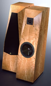
I find those speaker just strange. Avalons for instance.
In an ideal world the centre-to-centre of any 2 drivers at teh XO point should be less than a quarter wavelength.
At frequencies where tweeters XO this is in practise near impossible to do (even a coax will have a front-to-back distance greater than a quarter wavelength) so as close as possible is a necessity AFAIC.
dave

Some specific examples of designs you're curious about would help.
Just happened to see a Darko video with new Monitor Audio silver 100. Granted the distance between hi/low drivers is nothing like the Avalon above, why leave that 1/2 inch space between them? Why not butt the flanges right up against each other?
https://www.crutchfield.com/S-sM3rV...MI0IbRlbGh-gIVJOGGCh3yTgUUEAAYASAAEgJSC_D_BwE
Half inch space could be a manufacturing thing.
I thought about that but...jeez...it's 2022....the CNC doesn't care.
If there's a brace (or wall for sub-enclosure) between drivers, spacing them out a bit is the easiest/cheapest way to handle that. It also leaves more material in the brace/wall/baffle.
Sometimes tear-out around small features or finishing issues drive decisions like this also.
Sometimes tear-out around small features or finishing issues drive decisions like this also.
While I agree that the driver spacing is a bit wacky, a woofer height like that sometimes improves measured in-room frequency response, so I see some utility to that aspect.I find those speaker just strange. Avalons for instance.
I've visited dozens of speaker manufacturers at various audio shows, and have consistently seen them make numerous mistakes. Dave Smith made an offhand comment in his thread about arrays, where he'd mentioned that he recommended using shading to a manufacturer of loudspeaker arrays and they didn't know what it is.
So the most logical answer: they don't know any better.
As for small differences in spacing, that is sometimes done on purpose and for a good reason. Sometimes you know what the cabinet is going to look like and offsetting by an inch or two yields better response.
One other possibility - back before we had lots of software to tweak crossovers, the spacing ratios were coming from textbooks. For instance, if you have a 6.5" woofer and a 1" tweeter, you may have used a gap of 6.5" to achieve a "textbook" crossover. Nowadays that's less common because we can tweak the crossover components and come up with a slope that isn't textbook to compensate for a spacing ratio that isn't textbook.
Some even say some ratios should be avoided as 1/2 WL, and 1.1 or 1.2 WL spacing at cut off instead sounds best if 1/4 is not acheivable.
I am not sure however about the woofer and mid spacing above the Schroeder room frequency...
I am not sure however about the woofer and mid spacing above the Schroeder room frequency...
Food for thought - wider than conventional CTC spacing may help with power response:
https://www.diyaudio.com/community/threads/new-project-tower-3-way-with-twin-8s.378223/post-7079820
https://www.diyaudio.com/community/threads/new-project-tower-3-way-with-twin-8s.378223/post-7079820
I've heard the same thing about avoiding certain ratios. One half wavelength in particular.
The thing those people don't consider is moving one driver forwards or backwards changes the phase, and the slope of the xover changes the phase.
For instance:
I was talking to someone on an audio forum about 15 years ago, and I mentioned that 1st order filters were ideal to maintain phase. The person I was talking to brushed off my comment and basically said "you can get great phase response with high order filters if you compensate for the phase delay introduced by offset."
I'd never heard of this in my life, but I did the research... and they were right. In particular, check out LeCleach's "crossovers - a step further."
About three years ago I was at an audio show, and an actual manufacturer of expensive audiophile speakers said that first order filters were the ONLY way to maintain phase. I repeated what I'd been told 12 years earlier - that you can maintain phase using higher order filters if you compensate using offset - and the designer of these $10,000 speakers looked at me like I had two heads. He didn't get it at all.
And I've seen that same "mantra" repeated in dozens of audio magazines.
I've visited dozens of speaker manufacturers at various audio shows, and have consistently seen them make numerous mistakes. Dave Smith made an offhand comment in his thread about arrays, where he'd mentioned that he recommended using shading to a manufacturer of loudspeaker arrays and they didn't know what it is.
So the most logical answer: they don't know any better.
As for small differences in spacing, that is sometimes done on purpose and for a good reason. Sometimes you know what the cabinet is going to look like and offsetting by an inch or two yields better response.
One other possibility - back before we had lots of software to tweak crossovers, the spacing ratios were coming from textbooks. For instance, if you have a 6.5" woofer and a 1" tweeter, you may have used a gap of 6.5" to achieve a "textbook" crossover. Nowadays that's less common because we can tweak the crossover components and come up with a slope that isn't textbook to compensate for a spacing ratio that isn't textbook.
John> what do you think of the 1.2-1.4x crossvoer wavelength idea getting popular? I did some testing on a prototype to look at the vertical off axis, which I've taken more interest in a few years ago. https://www.diyaudio.com/community/...r-cnc-3d-printing.318190/page-57#post-7107363
Here are VC sims that moved me to try this. First is what I landed on for the prototype (middle left window is vertical responses + in-room) and the next is as close a ctc as I could manage:
I've seen promising results from sims, but I don't do much with conventional speakers, so the wide spacing doesn't really appeal to me. I mostly mess around with arrays and Unity horns, and wide spacing in those can generally be avoided. Basically we use a pile of small drivers to replace a large driver, and because our woofers are so small, it's not so hard to get spacing ratios under 0.7x
yeah, knew that 😉 . Was faster to wrote for my basic english speaking . I had already asked the same as the op and had such answer from "them" (was Timuiku iirc) 🙂Not only 'some say', they back it up and the threads are here to read. Like HifiJim's thread. Couldn't find the relevant posts from Kimmo Saunisto and Fluid tho.
Last edited:
Patrick Bateman,
If you talk also about horizontal offset so time impulse alignement and Z reference at cut off, I am not sure it is equivalent to phase tracking.
At least my understanding is very low about that. The difference I read is the physical time offset is more constant VS phase tracking relative to the distance change of the listeners. (means we should consider more often slanted front baffle or stepped one)
I am not sure but is the op does not talk about vertical lobyng as well for his question about ctc (so it is also relative to the filter order : a 1st slope is offsetting toward the ceilling the lobe , is it what you talk about John ?
The OP is not as knowledgable as the majority of posters. The OP is sitting back and learning 😉the op does not talk about vertical lobyng
After doing a lot of simulations, I came to an understanding of why Kimmo recommended a CTC spacing of 1.2 x wavelength.
Of course the best solution is 1/4 x wavelength, but that is not possible with most tweeters. In a 3-way, it is definitely possible between a woofer and a mid, but not from mid to tweeter.
So if we can't get 1/4 wavelength spacing, it seems like the next best option is 1.2 wavelength... why? well, it seems to me that it pushes the vertical nulls into frequency bands which offset the horizontal polar response of a typical crossover. The vertical and horizontal polar responses complement each other and result in a smooth even power response.
With a typical mid and tweeter pushed as close together as possible, the CTC spacing often ends up between 0.6 to 1.0 x wavelength, and this is a region to be avoided if possible. The vertical nulls will now add to the horizontal dip in power at certain frequencies, the the result is a dip in the power response.
j.
This is very helpful, thank you.With a typical mid and tweeter pushed as close together as possible, the CTC spacing often ends up between 0.6 to 1.0 x wavelength, and this is a region to be avoided if possible. The vertical nulls will now add to the horizontal dip in power at certain frequencies, the the result is a dip in the power response
Looks exactly as expected - a huge hole appears around the mid-tweeter crossover frequency when you become only slightly off the vertical axis. The horizontal power response depends on the drivers used so this case is more coincidental than a valid rule of thumb. If you use a 2" dome to cover up to 2kHz instead of a 7" midwoofer then you'll be solving a problem that doesn't exist. There is no guarantee that power response in a room matches anechoic measurements either, so you may be making compromises over how much sound is radiated to the sides when that sound may be entirely nulled out in a real room anyway.Food for thought - wider than conventional CTC spacing may help with power response:
https://www.diyaudio.com/community/threads/new-project-tower-3-way-with-twin-8s.378223/post-7079820
I wouldn't be compromising what happens in the first 30-45degrees off axis in the vertical directions, just to provide a minor improvement to the calculated power response. You don't want all the vocals to disappear into a black hole whenever you change from a seated to standing position.
Last edited:
- Home
- Loudspeakers
- Multi-Way
- Distance between drivers...am I missing something?