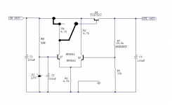
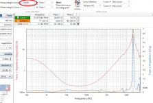
when i probe the output of this regulator, i get a 5mVp-p wavy response, as if the scope probe is not connected.
i was expecting a straight line, maybe a tiny amount of noise.
load is around 10mA, input 58V, output set for 48V.
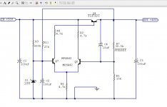
(cct is from a JLH power amp supply cira 1984)

i was expecting a straight line, maybe a tiny amount of noise.
load is around 10mA, input 58V, output set for 48V.
(cct is from a JLH power amp supply cira 1984)
Hi
This circuit is rather sensitive for ripple across D1 as any ripple here will be multiplied by 4.85 on the output.
Try to measure this - but beware given your 5mVpp output ripple it is expected to by just around 1mVpp.
If this is the issue then you can reduce the ripple by changing R3 to maybe 1M and then add a new resistor - f.ex. 22k - from the base of Q7 to the output of the power supply.
This change will reduce the ripple current though D1 as most current will come from the stabilized output and consequently the ripple voltage across D1.
Another improvement would be to add a capacitor in parallel with R7 - 100uF would be enough.
This will reduce abovementioned multiplication of the ripple across D1 to 1.
Cheers, Martin

To see if the main noise contributor is the Zener, add a 1k resistor between D1 and C2
to make a more effective low pass filter.
to make a more effective low pass filter.
This simple regulator’s performance is limited by both voltage reference ripple at the Q7 base and by total negative feedback. Proposed addition of capacitor in parallel with R7 is likely to bring biggest improvement with resulting output ripple of 1 mV or less.
I don’t expect that improving voltage reference will bring desired performance but there is a simple upgrade available – replacing R3 with CCS in form of Current Regulator Diode (packaged JFET CCS) as: Semitec E-102
Replacing R7 with CRD, according to my measurements, will bring 30 dB improvement at the voltage reference, but likely much less at the regulator output.
5mV ripple in a power amplifier supply is not large. As said, here limited by non-infinite gain in the error amplifier. If you have 5V raw ripple, and gain of 1,000 in this regulator, that's 5mV out. If the power amp has 1000:1 PSRR, that's 5uV at the speaker, which is pretty small.
It should help a lot to add an RC filter at the regulator input. After the 100uF, add a series resistor (around 100R),
and another shunt 100uF.
and another shunt 100uF.
If the scope's trigger can be set to LINE and if that makes the wavy waveform stand still, then you know it is indeed due to the circuit's finite ripple rejection.
thanks for the responses, i will try a capacitor in parallel with R7 first.
if i connect R4 to +58V and Q4 base to Q7 collector, will it change the performance for better or worse?
if i connect R4 to +58V and Q4 base to Q7 collector, will it change the performance for better or worse?
if i connect R4 to +58V and Q4 base to Q7 collector, will it change the performance for better or worse?
If this is indeed JLH's correct schematic, then I would not change that. He knew what he was doing.
But do add the RC filter at the HV input if you want lower ripple noise.
if i connect R4 to +58V and Q4 base to Q7 collector, will it change the performance for better or worse?
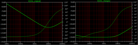
Fun fact – performance is the same with both variants. We were guessing a lot, while LTSpice simulation is better than guesswork (even if guesswork is knowledge and experience based).
So, this circuit is really not great, but it was perfectly OK for an intended use with a power amplifier. Sim calculates 100 Hz PSRR as 47 dB, probably being 40 dB or 100x with the real circuit. Messing with the voltage reference brings zero improvement. Adding capacitor, in parallel with R7, brings 20 dB PSRR improvement at low frequencies only, so expected ripple reduction will be around 1000x.
Another point worth to mention is that this regulator is LDO type and could operate at 1 V or less of input – output voltage difference.
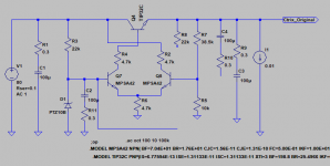
Jack, study Figure 2 schematic of post #13 carefully. It's got a positive feedback loop. You've used the "NPN" symbol to represent the TIP32C which assuredly is a PNP transistor as attached below.
You've also swapped the emitter and collector of the pass transistor. In post #1 of this thread, the input is emitter and the output is collector. Your schematic in post #13 is the reverse.
Because of these unusual deviations, I doubt that simulations of your schematic correlate to real world behavior. I believe the circuit's wrong and its simulation results are untrustworthy.
_
Attachments
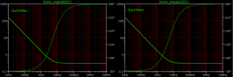
130 dB PSRR flat?
Why Walter Jung and Jan Didden had to bother with a super-regulator? 🙂
Unfortunately, it's only LTSpice quirk. For a moment, I thought that we have a winner.
Why Walter Jung and Jan Didden had to bother with a super-regulator? 🙂
Unfortunately, it's only LTSpice quirk. For a moment, I thought that we have a winner.
Last edited:
I f'd up!Jack, study Figure 2 schematic of post #13 carefully. It's got a positive feedback loop. You've used the "NPN" symbol to represent the TIP32C which assuredly is a PNP transistor as attached below.
You've also swapped the emitter and collector of the pass transistor. In post #1 of this thread, the input is emitter and the output is collector. Your schematic in post #13 is the reverse.
Because of these unusual deviations, I doubt that simulations of your schematic correlate to real world behavior. I believe the circuit's wrong and its simulation results are untrustworthy.
_
Yupp, I had to use a bit lower output voltage as my current injector is limited, but there is evidence of instability, 19 V out, 25mA load :Because of these unusual deviations, I doubt that simulations of your schematic correlate to real world behavior. I believe the circuit's wrong and its simulation results are untrustworthy.
_
Attachments
- Home
- Amplifiers
- Power Supplies
- discrete regulator: noise, unstable or ok?