Hi everybody
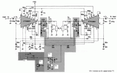
I have started this thread with a circuit that I still dont know how its working,thought people dealing with solid state and discrete transistors may help,looking to the internal circuitry of the STK4040V may help you people.
What I want to know,how is T5 supposed to work as the protection element.That will activate the latch composed of T3 and T4,hence T1 will work and turn off the internal current mirror in the STK4040V.
Now,does any body can explain how is T5 working by some theoritical and mathematical basis,and is there any other circuits that might do the same job.
BR
Attachments
It is not protectin circuit, it is probably " automute " , when amps are switch off. Protection circuity must have output relay.
When the voltage across the 0.22ohm resistor reaches a critical level for long enough, the cap across T5:s BE will have time to charge to 0.7 volts, and then the latch is triggered. The time constant of 220 ohms and 3.3uF is 0.73 ms, so with 1 volt across the 0.22 ohm resistor the protection will kick in in approximately that time frame. 1 volt across 0.22 ohm is 4.55 amps, so the circuit is short circuit protected to a voltage somewhere in that region.
A point to note is that it only measures current in one direction, so it's hardly fool proof.
Rune
A point to note is that it only measures current in one direction, so it's hardly fool proof.
Rune
Thank you for replies
Ok runebivrin,I already know that this circuit works in the -ve direction only,then how can I design a circuit that acts on both the +ve and -ve directions,but I think its fool proof too.
Can any one suggest another protection circuit for such ICs,so one can use them with any audio power IC as he wants,and determine the current at which this circuit will work.
BR
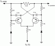
I figure it might work if you simply add a copy of the circuit around T5 (220ohm, 3.3uF, 1.8kohm and diode), connect the collectors together and swap emitter and other side of the 220ohm resistor.
That way you've essentially got two detectors back to back.
Rune
That way you've essentially got two detectors back to back.
Rune
More Explaination please
Hi runebivrin
Would you please explain more about what you said above,you mean to switch the connections of the 220 Ohm resistor and emittre,if so,hoe is it going to work.
Thank you for your reply
Hi runebivrin
Would you please explain more about what you said above,you mean to switch the connections of the 220 Ohm resistor and emittre,if so,hoe is it going to work.
Thank you for your reply
- Status
- Not open for further replies.
- Home
- Amplifiers
- Solid State
- Discrete protection circuits

