Hi Sigurd,
what I don't get is how the common mode rejection works when using two bridged boards with this circuit.
Rüdiger
what I don't get is how the common mode rejection works when using two bridged boards with this circuit.
Rüdiger
Paul,
I will look out the Maclaren circuit in the weekend, and put something up for you, time permitting. I think it sounds pretty good, but I am biased!
Mostly it uses BC550 and BC560 (obtainable anywhere), except for the input stage, which uses Renesas 2SA1084/2SC2546. In the UK they are available from Farnell or Dalbani. RS seem to have the equally acceptable 2sa1085/2sc2547 (although their website is in a real muddle, so I don't trust them).
I don't know which US suppliers are convenient for you, but if all else fails, both RS and Farnell have US operations.
Do you have the article number by any chance?PigletsDad said:....Renesas 2SA1084/2SC2546. In the UK they are available from Farnell....
I can't find these 😕
peranders said:Do you have the article number by any chance?
I can't find these 😕
I can't find them either. They had them maybe 6months ago, when I last looked for them. Sorry.
At least RS have the 1085/2547 option (give or take some website confusion.)
Dalbani quote the 1084 as out of stock, but they have the 1085 in. They have both the 2sc2546 and 2sc2547.
I will go back and edit my older posts to correct the mistake.
last time i checked (a month or 2 ago), you could still get 2SK369 JFETs and cheaply too.
no p channel complement, but as was previously stated, if all you need are very low noise n channel parts, you could do a whole lot worse than these ...
mlloyd1
no p channel complement, but as was previously stated, if all you need are very low noise n channel parts, you could do a whole lot worse than these ...
mlloyd1
the Pass Pearl requires the use of unobtainium too.
The Pearl has one 2SK389 but it's two channels are in parrallel (i.e. not in a diff. pair) so you can easily substitute it with two 2SK170, and these are still available! 2SK370 seems to be the same device in a slightly different package, if you can get this one easier. Some level of matching would not hurt but it is not absolutely necessary.
Bear in mind that the 2SK370 has a lower Pd rating. As long as you can live with that, it's a good alternative.
Grey
Grey
OK, no more esoterica. I just don't think people should put their phono projects on a permanent back burner because they can't source what some call the "occult" parts.
In full disclosure, I personally use a zero feedback phono stage using the really unobtanium Toshiba matched pairs with the huge tophat metal case. I got them at Akihabara 20yr. ago.
In full disclosure, I personally use a zero feedback phono stage using the really unobtanium Toshiba matched pairs with the huge tophat metal case. I got them at Akihabara 20yr. ago.
scott wurcer said:
In full disclosure, I personally use a zero feedback phono stage using the really unobtanium Toshiba matched pairs with the huge tophat metal case. I got them at Akihabara 20yr. ago.
I'm in the process to build/design a zero feedback phono stage with the latest unobtaniums 389/109.
Are you talking about the 2sk146/2sj73 ?
And talking about 'full disclosure', are you using 2 or 3 gain blocks?
More infos would be nice, eg. bandwith, first stage gain, noise, ...
Rüdiger
Onvinyl said:
I'm in the process to build/design a zero feedback phono stage with the latest unobtaniums 389/109.
Are you talking about the 2sk146/2sj73 ?
And talking about 'full disclosure', are you using 2 or 3 gain blocks?
More infos would be nice, eg. bandwith, first stage gain, noise, ...
Rüdiger
That's right on the devices. It's been mothballed for a couple of years, but as I remember it was a gain stage with the high frequency pole followed by a stage with the rest of the RIAA time constants. It went into a Jung 823/815 line stage that Walt was kind enough to give me, everything on Walt's super regulator. I built the thing in a flurry of activity and then lost the schematics.
scott wurcer said:
It went into a Jung 823/815 line stage that Walt was kind enough to give me, everything on Walt's super regulator. I built the thing in a flurry of activity and then lost the schematics.
Hehe, so I'm not the only one who can't remember what the heck he did on that board the week before... 🙄
Anyway, it's cool to know that it is possible to build an open-loop phonostage.
Rüdiger
A hitch - cannot disclose Maclaren circuit
Sorry, guys. I looked out my Maclaren stuff, and found my letter of engagement, where I agreed not to disclose the circuit, nor to build it commercially myself. Now the NZ company (Zetka Enterprises) that made the Maclaren stuff stopped trading in the early 90s, but I think I am still bound by my original undertaking.
Of course, the agreement doesn't stop me disclosing some other circuit, which is different to the Maclaren design, but maybe shares some general features with it.
So I will do a new design just for diyaudio. The general topology is as follows:
Two stage design:
All bipolar transistor. For the MC input stage, uses Renesas 2sa1085 and 2sc2547. The rest are BC550 and BC560. Complementary symmetry circuits.
First stage captures the noise figure, and raises the levels to the point that noise in the second stage is not an issue, but overload is also unlikely. The first stage is non-inverting, and has a flat frequency response (give or take any RF rolloff you elect to go for). I will give instructions for how to tailor the values to match different classes of cartridge. This stage is entirely DC coupled. 6 transistors/channel.
The second stage provides the rest of the gain and the RIAA equalization. This is an inverting stage. The HF rolloff is passive, and forms part of the input network. I prefer to stick with the actual RIAA curve, but if you want to add a zero at 50kHz to match the Neumann cutting head, it needs 1 extra resistor. The two low frequency time constants form the feedback network. 6 transistors/channel. There is a coupling capacitor between first and second stages, which sets the LF rolloff.
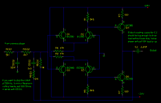
First stage.
There are obvious things that could be changed to improve the circuit in various ways, but they also make it more complex.
The PSRR is limited in this version, so the +/-12V supply must be fairly low noise.
Values shown are for low impedance MC cartridges of typical output (say 300 to 700uV). If you have a very low output one like some Ortofons, increase R4.
RF problems vary widely, and the value of C3 that you want or need may be very different to that shown.
Second stage will follow once I draw it up.
Attachments

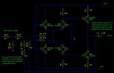
The equalisation stage.
The components with EQ in the name (like CEQ1 etc.) are involved in setting the RIAA equalization, and should be close tolerance - 1% resistors, 5% or better capacitors.
The signal levels are higher, so the PSU requirements for this stage are not so fussy. Note that this runs on +/- 24V. If you are happy to do without 6dB of headroom, you could use +/- 12V. In that case change the current setting resistors for the input pairs from 47K to 24K, to keep the operating current the same.
Attachments
Very interesting design!!
Still need to think more about it.
By the way, CEQ2 appears twice in the equalisation stage; I guess only the 3n3 cap is the real CEQ2?
Do you plan to build this circuit? I would be very interested in its performance.
All the best, Hannes
Still need to think more about it.
By the way, CEQ2 appears twice in the equalisation stage; I guess only the 3n3 cap is the real CEQ2?
Do you plan to build this circuit? I would be very interested in its performance.
All the best, Hannes
Hannes,
Thanks for spotting that. Here is the correctly labelled version.
I built the first version of a design like this back in 1982. The Maclaren version was sold between 1985 and about 1989 (I think), and replaced by a design by their in-house engineer.
Measured performance was pretty good. Noise is low - about 0.7nV/rt Hz. Distortion is very low. Overload margin is very good. EQ accuracy is spot on (better than 0.2dB) if you get accurate components, with just a little in band bass loss from the choice of 16Hz for the LF -3dB point.
The design has no electrolytic caps in the signal path, only film, and the crucial input stage is all DC coupled. I won't comment on the subjective performance, as I am a biased observer, but still use the production version.
Attachments
If you ever build this amp you will probably be aware of your offset problems => hugePigletsDad said:The design has no electrolytic caps in the signal path, only film, and the crucial input stage is all DC coupled. I won't comment on the subjective performance, as I am a biased observer, but still use the production version.
AC coupled or DC servos are musts.
Peranders,
It is AC coupled, just with film caps. The impedance scales have been chosen so that film values are practical.
I absolutely agree that a DC coupled phono preamp would be a disaster.
In fact, one reason for the two stage design is to keep the gain in each individual design down to a level where the DC offset is bearable. The first block has DC gain of 100 - 40dB. Assuming the input transistors are matched to a few mV (which is reasonable in practice), the offset at the output of the first block is maybe half a volt or so. The second section is AC coupled at input and output. The main driver of offset is the input bias current (about 0.5uA) in the feedback resistor (1M). Again the output offset is of order 0.5V.
In this design you must not remove the coupling cap between the two blocks.
- Status
- Not open for further replies.
- Home
- Source & Line
- Analogue Source
- Discrete phono preamp designs?