Hi stein
I chose jfet ips because i need very high input impedance and need to be free to choose feedback circuit independent of input circuit without issues regarding output offset..... and i do prefer jfet sound
I chose jfet ips because i need very high input impedance and need to be free to choose feedback circuit independent of input circuit without issues regarding output offset..... and i do prefer jfet sound
I am trying to avoid any imbalance in the currents of the mirror as I found these are determinant for low THDHi Ricardo
Thank you, but to see it I have to install LTSpice and that is not going to happen.
I have looked on some of your previous posts and can see your "design".
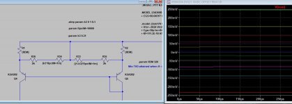
I think you should try a 10k pot. with the wiper connected at the positive rail and the element between R1 and R2 see the drawing, that should null the DC offset at the output.
Why would you not use the idea provided by Damian ?(This i my opinion: I would not null the offset like Damian is suggesting and in case you intend to use a DC servo I would not connect it to the negative input.)
Where would you connect the servo injecting current ?
Would you please suggest a better way to design this DOPA ?One question why do you select this design and what is the reason you have chosed to use JFET ips instead of BJT?
In my opinion, if you for some reasons prefere JFET ips instead of BJT there are much better ways to design a circuit with lower noise and THD that will fit into a 990 package.
Stein
I built it this way because I am familiar with the LIN topology and know how to reduce THD in a blameless type design...
I simmed your connection and it works without affecting THD.... Thank you so much🙂
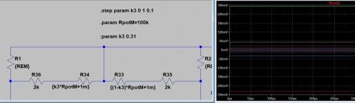
I see that circuit is provided in the OPA627... I added the 2k resistors to avoid accidental large offset when setting the trimmer to one of it's ends.... what would be the best resistor combination to ease the nulling offset trim ?
I see that circuit is provided in the OPA627... I added the 2k resistors to avoid accidental large offset when setting the trimmer to one of it's ends.... what would be the best resistor combination to ease the nulling offset trim ?
Attachments
Last edited:
I simmed your connection and it works without affecting THD.... Thank you so much🙂
I'm glad I could help you.
Increasing the pot value just makes trimming easier
Yes that is right.
Stein
I am now populating another board with the modified trimmer arrangement and without servo... hope it works as expected.
I am now populating another board with the modified trimmer arrangement and without servo... hope it works as expected.
I see no reason why it shouldn't work.
It's a good idea to use a multi-turn pot and trim the DC when the transistors have reached the working temterature.
Stein
It works with the 2sc2240 but it becomes prone to oscillations @ 8.5MHz.... cured with an increased input resistor.
I can now null ops offset ... stable @ 0.1mV
I can now null ops offset ... stable @ 0.1mV
Last edited:
It's good to see that it worked as I expected.
Next time you design an DOPA you should consider looking at what transistor to use in the different places, it's not so that it's best to use high voltage, high hfe transistors all over the place.
BTW: I see that you asked EUVL "Patric" for help on a different matter, please note; EUVL is here for two good reasons, Number 1: selling, Number 2: asking for help to have more to sell. 🙄
I'm not surprised that he didn't answer you.😉
Stein
Would you please advise on what transistors i should replace for best operation ?
Hmm
I said: Next time you design an DOPA you should consider looking at what transistor to use in the different places .............
That was meant as a good advise for you if you plan to "design" a new discrete opamp.
I didn't say that I would design it for you, but it's a good advise and you should consider it when it comes to noise, stability and THD.
Stein
I really do not want you to design a dopa for me.
I selected the transistors based on low noise, low cob for the vas, power dissipation and speed for the ops and low noise and high inpedance for the ips.
The layout is carefully designed to avoid noise and oscilations.
Maybe you know better so that is wy i asked.
I selected the transistors based on low noise, low cob for the vas, power dissipation and speed for the ops and low noise and high inpedance for the ips.
The layout is carefully designed to avoid noise and oscilations.
Maybe you know better so that is wy i asked.
- Home
- Source & Line
- Analog Line Level
- Discrete opamp offset trim