Thank you!Nice!
How would I test that using LTSpice?What about 19+20k IMD?
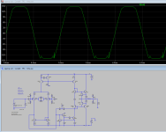
attaching screenshot with 20V 1khz signal fed to the inputAnd how does it clip?
Attachments
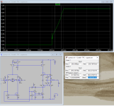
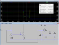
I was able to get slew rate from square wave simulation - I just placed two pointers and looked at the slope. Screenshot attached - shows 8 V/us - that is from a newly redesigned versionApply a square wave input whose amplitude is 1 volt and whose rise time is 50 nanoseconds; observe output waveform at 50nsec per horizontal division; slew rate = (delta_Vout / output_rise_time)
Attachments
Double check that you are definitely fully-current-steered; a necessary condition to measure slew rate.
The easiest way to do so on the #22 schematic, is to plot the collector currents of the two NPNs which form a current mirror in the input stage. If you're fully-current-steered, the collector current of one NPN mirror device will drop to ZERO and the collector current of the other NPN mirror device will hit a plateau equal to 100% of the stage current provided by the top PNP current source. When that happens: yep, yer slewing.
The easiest way to do so on the #22 schematic, is to plot the collector currents of the two NPNs which form a current mirror in the input stage. If you're fully-current-steered, the collector current of one NPN mirror device will drop to ZERO and the collector current of the other NPN mirror device will hit a plateau equal to 100% of the stage current provided by the top PNP current source. When that happens: yep, yer slewing.

Double check that you are definitely fully-current-steered; a necessary condition to measure slew rate.
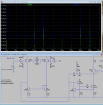
Attached are screenshots of results
I have fed opamp square wave 1Vpp and 10Vpp
And 1khz sinewave 2Vpp
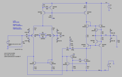
LTP current 621 uA
VAS current is 1.97mA
OPS current is 2.14mA
Are those graphs is what we are looking for to see full current steer?
Thank you!
Attachments

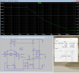
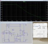
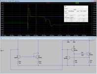
Two Pole Compensation was fixed by adding 100n cap to smooth the peak in OLG graph.
Phase margin is at 37 deg
OLG at 20kHz is 80dB
OLG at 100Hz is 133dB
Noise is at 2.16 nV/rtHz
THD at 1kHz and 2Vpp input is 0.000001% or -160dB
20kHz is at 0.000024% or -132dB
I say this is pretty darn good opamp even if compared to commercial offerings!
Phase margin is at 37 deg
OLG at 20kHz is 80dB
OLG at 100Hz is 133dB
Noise is at 2.16 nV/rtHz
THD at 1kHz and 2Vpp input is 0.000001% or -160dB
20kHz is at 0.000024% or -132dB
I say this is pretty darn good opamp even if compared to commercial offerings!
Attachments


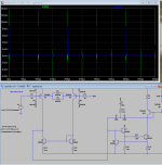
Your graphs look nice and neat. Mine for some reason have many strange moves and spikes.
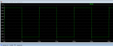
I fed 1Vpp 10khz square wave.
Q5 and Q11 are current mirror transistors.
Both collector currents are the same.
Attached separately zoomed up and down slews.
Thanks
I fed 1Vpp 10khz square wave.
Q5 and Q11 are current mirror transistors.
Both collector currents are the same.
Attached separately zoomed up and down slews.
Thanks
Attachments
They should be - it's a current mirror. It does however look like the amp is slewing - compare the current mirror currents with that of the tail current source.Both collector currents are the same.
- Home
- Source & Line
- Analog Line Level
- Discrete OPAMP based on Lin topology with Two Pole Compensation