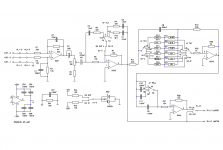
Seems that post#1 runs its output stage transistors at 2X the bias current of Bryston's output stage in post#16.
However Bryston uses medium power transistors in TO126 packages for their output stage, whereas post#1 uses wimpy TO92 transistors. Twice the power at half the rating, hmmm.
However Bryston uses medium power transistors in TO126 packages for their output stage, whereas post#1 uses wimpy TO92 transistors. Twice the power at half the rating, hmmm.
At +/-33V though - normal opamps are +/-18V or so into 600 ohm loads, not exactly burning it up at 25mA peak - of course you might have to consider over current protection when considering thermal aspects of the design as that's the operating condition to worry about, not bias.However Bryston uses medium power transistors in TO126 packages for their output stage
My idea here is to make these op-amps perform as well or better than the original design. My main problem is finding a replacement for the outdated BC413/415 transistors.Seems that post#1 runs its output stage transistors at 2X the bias current of Bryston's output stage in post#16.
However Bryston uses medium power transistors in TO126 packages for their output stage, whereas post#1 uses wimpy TO92 transistors. Twice the power at half the rating, hmmm.
These two designs are from Bryston. So they appear to be two different versions of the same opamp, for two different products. Albeit with a different supply. one is 33V and the other is 24V. I'm guessing even with that current setup it's not enough to be a problem, maybe it has to do with the noise specs for each transistor, I don't know, guessing here.
My goal is to find a pair of transistors that looks as good as the BC413/415 stated in their datasheet, but seems to be more difficult than I thought...
The higher the voltage the worse thermal drift issues will be, and the harder to get rock solid protection built-in too. One of
the brilliant features of (nearly) all opamps is full short-circuit protection.
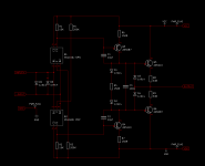
One issue I've just noticed is the lack of back-to-back diodes across the inputs in either design - this is essential for a low noise opamp to prevent the input transistors having their EB junctions undergo reverse breakdown - this rapidly erodes noise performance and any BJT used for its low noise needs this protection across its base-emitter junction (or for differential pairs you can simple use the two diodes across the inputs).
See the graph on page 32 of this lecture: https://www.uio.no/studier/emner/matnat/ifi/INF5460/h16/undervisningsmateriale/f8-1p.pdf
You'll note bipolar opamps like the NE5532 have these diodes fitted if you look in the datasheet schematic. The AD797 schematic doesn't show them, but the absolute max. section says the differential input voltage must stay within +/-0.7V which means they are there.
the brilliant features of (nearly) all opamps is full short-circuit protection.
One issue I've just noticed is the lack of back-to-back diodes across the inputs in either design - this is essential for a low noise opamp to prevent the input transistors having their EB junctions undergo reverse breakdown - this rapidly erodes noise performance and any BJT used for its low noise needs this protection across its base-emitter junction (or for differential pairs you can simple use the two diodes across the inputs).
See the graph on page 32 of this lecture: https://www.uio.no/studier/emner/matnat/ifi/INF5460/h16/undervisningsmateriale/f8-1p.pdf
You'll note bipolar opamps like the NE5532 have these diodes fitted if you look in the datasheet schematic. The AD797 schematic doesn't show them, but the absolute max. section says the differential input voltage must stay within +/-0.7V which means they are there.

Well I think I'll give the new Toshiba part a shot, at least it has some noise specs on the datasheet. I'll try to put the protection diodes on the board, it seems like a good idea.The higher the voltage the worse thermal drift issues will be, and the harder to get rock solid protection built-in too. One of
the brilliant features of (nearly) all opamps is full short-circuit protection.
One issue I've just noticed is the lack of back-to-back diodes across the inputs in either design - this is essential for a low noise opamp to prevent the input transistors having their EB junctions undergo reverse breakdown - this rapidly erodes noise performance and any BJT used for its low noise needs this protection across its base-emitter junction (or for differential pairs you can simple use the two diodes across the inputs).
See the graph on page 32 of this lecture: https://www.uio.no/studier/emner/matnat/ifi/INF5460/h16/undervisningsmateriale/f8-1p.pdf
You'll note bipolar opamps like the NE5532 have these diodes fitted if you look in the datasheet schematic. The AD797 schematic doesn't show them, but the absolute max. section says the differential input voltage must stay within +/-0.7V which means they are there.
I may need some help on how to get this device to work within that 1db noise window.
Correct if I'm wrong, with this source resistance, I should choose collector/emitter resistors so that Ic is about 20mA?. What would be the best way to do that?
Thanks again for the help!
Attachments
Which source resistance? I see 20k's and 1k's in various places.Correct if I'm wrong, with this source resistance, I should choose collector/emitter resistors so that Ic is about 20mA?.
For low current noise you want low currents, current noise goes with the square root of current. For low voltage noise higher currents are better - you look at the datasheet to pick the sweet spot for the impedance you are targetting.
How do you figure that?with this source resistance, I should choose collector/emitter resistors so that Ic is about 20mA?
The system hiss level is dominated by R1 R2. IF low noise is really a goal, you want a better circuit topology (before you even think about DOA design).
Well, the goal really is to get these op-amps to work with at least same performance as they do with the BC413/BC415.How do you figure that?
The system hiss level is dominated by R1 R2. IF low noise is really a goal, you want a better circuit topology (before you even think about DOA design).
I can see that it's not a very sophisticated design (size is really a limitation on this too).
I'm not trying to design an opamp here, I thought I could get some help on how to get this Toshiba part to work on this design because I have a bunch and it seems like a good candidate. However, I'm not quite sure how to get the correct values for R1 and R2.
This are my main studio speakers. DOA 1 and 2 go bad quite often for some reason and start to make noises, (maybe the lack of protection diodes as Mark pointed out)
I used to replace the diff pairs to solve the issue but I run out BC4XXs transistors.
thanks!
Did they? In any case: a BJT's hiss is known from physical constants, unless it has dirt, a defect. In 1969, transistor processes were un-clean. In this day of million-transistor CPUs, Silicon processing is reliably clean. Are "ALL" transistors low-hiss? No process is perfect. But hiss-testing is VERY expensive. And 99.44% of users today do not care. Why would they pay for hiss-test? When even if they do care, 99+% of their products will be nearly minimum hiss?datasheet only shows the "Typ." value while the old ones used to show the Maximum
Note that "known from physical constants" implies that different transistors of the same junction area will have the same noise curves. Unless they have excess resistance (few do today). So you mostly do NOT have to adjust operating conditions for the general-purpose 100mA-500mA small signal devices. As long as you are in the BJT sweet-spot 1k-50k. Yes, as you get into 10 Ohm MC cartridges even a few Ohms parasitic matters, and you must be clever. High impedance also, though today we have excellent JFETs. And your 5k-20k is not "high" for modern high-hFE low-leakage BJTs.
Without thinking "is it 5k or 20k?", we can block-out that impedance range in pink. And tick-off the extreme 1dB NF points in blue. You will be 1dB NF for 10uA to 500uA. And the schematic suggests you are working at 117uA. Which is really as close to the middle of the 1dB NF ellipse as can be.
Attachments
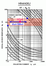
@PRR I worry that 117uA of tail current, evenly split between Q5 and Q6, produces a worrisome small voltage across collector resistor R2. So small that temperature induced variations in the VBE of transistor Q7, produce worrisome LARGE variations in 2nd stage DC bias current.
It's not my design. It does seem to multiply error in each stage, don't it? Maybe "shirtsleeve-only environment"?
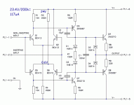
0.058mA*15k= 0.87V
2N5210 data: https://www.mouser.com/datasheet/2/149/2N5210-193106.pdf
Assume@25c @1mA, about 0.65V?
0.87V-0.22V= 0.22V across 150r makes 1.467mA, reasonable.
At 125C, 0.200V less Vbe, yes, this is a problem, if the weather is above boiling, and maybe on a hot day in the Mojave.
I can't see why they didn't just use the '5532 here.
0.117mA/2= 0.058mA117uA of tail current, evenly split between Q5 and Q6, produces a worrisome small voltage across collector resistor R2. So small that temperature induced variations
0.058mA*15k= 0.87V
2N5210 data: https://www.mouser.com/datasheet/2/149/2N5210-193106.pdf
Assume@25c @1mA, about 0.65V?
0.87V-0.22V= 0.22V across 150r makes 1.467mA, reasonable.
At 125C, 0.200V less Vbe, yes, this is a problem, if the weather is above boiling, and maybe on a hot day in the Mojave.
I can't see why they didn't just use the '5532 here.
This things get hot in there. they live between two gigant heatsinks of the power amp. More like no-shirt beach environment, not above boiling though...It's not my design. It does seem to multiply error in each stage, don't it? Maybe "shirtsleeve-only environment"?
0.117mA/2= 0.058mA
0.058mA*15k= 0.87V
2N5210 data: https://www.mouser.com/datasheet/2/149/2N5210-193106.pdf
Assume@25c @1mA, about 0.65V?
0.87V-0.22V= 0.22V across 150r makes 1.467mA, reasonable.
At 125C, 0.200V less Vbe, yes, this is a problem, if the weather is above boiling, and maybe on a hot day in the Mojave.
I can't see why they didn't just use the '5532 here.
The speakers are very (hiss) quiet as they are , untill the opamps fail then they start to make weird noises.
Guess I'll make these PCBs and test the new transistors, if it goes wrong I may transform it into a nice DIP adaptor hahah.
Btw, Thanks for the circuit explanation!
I do not see why those transistors should be failing. Are they getting 110V spikes from somewhere?
How would you implement dc trimming on this circuit? Make either of the 200k ohm trimmable?
I wanna try this circuit too but i rarely ever bother matching my transistors
I wanna try this circuit too but i rarely ever bother matching my transistors
Just to report that the Toshiba transistor pair (HN4C06J) ended up working very well on this opamp. Im thinking on using two of this opamps for another project as an output diff amp because I need a 24v opamp there.
I added the protection diodes at the input, but Im wondering if I need to change the output devices for increased output drive current. Any advice on how to improve this opamp desing are welcome, thanks!
I added the protection diodes at the input, but Im wondering if I need to change the output devices for increased output drive current. Any advice on how to improve this opamp desing are welcome, thanks!
What is not not doing well?Im wondering if I need to change the output devices for increased output drive current. Any advice on how to improve this opamp desing
How much current do you need? (Don't buy a 63Amp circuit to light a 0.046A LED-lamp.)
As shown it can do 36mA. Not limited by the transistor but by diode clamp and emitter resistor. How much do you need?
Ideally it should be able to drive a 600 ohm input transformer at around +32 dbu, with a long cable.What is not not doing well?
How much current do you need? (Don't buy a 63Amp circuit to light a 0.046A LED-lamp.)
As shown it can do 36mA. Not limited by the transistor but by diode clamp and emitter resistor. How much do you need?
It's for an output stage of a double balanced mic preamp
I'm building it on breadboard now to see how it goes...
thanks!
- Home
- Source & Line
- Analog Line Level
- Discrete Opamp advice