I'm the kinda guy who designs circuits when I have nothing to do.
So recently I designed an ABX switch box using discrete logic.
Here's my Conceptual Schematic:
It seems to work fine in my simple Java circuit simulator, but I'm not sure if this will really work.
So is there anyone with electronic experience who can give me some feedback?
(anything wrong, improvements?)
Notes:
Relays aren't drawn here because this simulator doesn't have the reed relays I'll be using.
The "ABX Switch" has a center-off position.
The "Randomize X Switch" is a Push-switch.
The "X" random is generated using a square wave and a human controlled "hold" switch.
Picture it like a wheel of fortune or slot machine if you will.
The "OR" gate in the center that's connected to its own input is used to hold the "X" status,
so that the status of "X" will be the same every time until the "Randomize switch" is pushed
EDIT:
I may switch the NOR gate for an OR gate and Discrete CMOS NOT Gate (Using 2 MOSFETs),
because Logic gates comes in packages of 4s.
Anyone know a small complementary MOSFET pair I could use?
(No surface mount packages)
So recently I designed an ABX switch box using discrete logic.
Here's my Conceptual Schematic:
An externally hosted image should be here but it was not working when we last tested it.
It seems to work fine in my simple Java circuit simulator, but I'm not sure if this will really work.
So is there anyone with electronic experience who can give me some feedback?
(anything wrong, improvements?)
Notes:
Relays aren't drawn here because this simulator doesn't have the reed relays I'll be using.
The "ABX Switch" has a center-off position.
The "Randomize X Switch" is a Push-switch.
The "X" random is generated using a square wave and a human controlled "hold" switch.
Picture it like a wheel of fortune or slot machine if you will.
The "OR" gate in the center that's connected to its own input is used to hold the "X" status,
so that the status of "X" will be the same every time until the "Randomize switch" is pushed
EDIT:
I may switch the NOR gate for an OR gate and Discrete CMOS NOT Gate (Using 2 MOSFETs),
because Logic gates comes in packages of 4s.
Anyone know a small complementary MOSFET pair I could use?
(No surface mount packages)
Last edited:
From a user point of view, what does he do to change from A to B to X? Reversible? How is the "final answer" and the actual option presentation recorded?
A nice analog ABX box would be a good thing to have!
A nice analog ABX box would be a good thing to have!
From a user point of view, what does he do to change from A to B to X? Reversible? How is the "final answer" and the actual option presentation recorded?
A nice analog ABX box would be a good thing to have!
The ABX Switch has 3 states, the 2 sides will give state A and B while the center position will give state X.
The states are changes simply by flicking the ABX switch.
The actual state of X can be seen via the "Actual status indicator" (refer to schematic), This is normally hidden from the user.
Thanks. If it's hidden, how is the choice recorded? Tough without a microcontroller... Could you add a few gates, let the user guess after he's switched back and forth enough times, and then a red or green LED comes on depending on whether he's right or wrong? The user then has to record his track record, so the controls for a third party aren't tight, but it can be useful as a training tool or individual curiosity (like the ABX function in foobar).
Thanks. If it's hidden, how is the choice recorded? Tough without a microcontroller... Could you add a few gates, let the user guess after he's switched back and forth enough times, and then a red or green LED comes on depending on whether he's right or wrong? The user then has to record his track record, so the controls for a third party aren't tight, but it can be useful as a training tool or individual curiosity (like the ABX function in foobar).
Unfortunately, it will have to be recorded by the user after guessing and before randomizing for the next guess. (Take a peek inside/behind the box maybe?)
While it's not hard for me to add a few memory registers to record X states (4 maybe), it'll get quite complex construction-wise without PCBs.
Since the whole point of this is that µCs are not required, people who don't have access to µC tools probably can't make PCBs either...
Just made a practical schematic:
Note: The ABX switch shown is a SP4T Rotary Switch because I couldn't find a SPDT switch with center-off in the library.
An externally hosted image should be here but it was not working when we last tested it.
An externally hosted image should be here but it was not working when we last tested it.
Note: The ABX switch shown is a SP4T Rotary Switch because I couldn't find a SPDT switch with center-off in the library.
Thanks. If it's hidden, how is the choice recorded? Tough without a microcontroller... Could you add a few gates, let the user guess after he's switched back and forth enough times, and then a red or green LED comes on depending on whether he's right or wrong? The user then has to record his track record, so the controls for a third party aren't tight, but it can be useful as a training tool or individual curiosity (like the ABX function in foobar).
Well, You asked and I delivered!
Here's an extension of my previous design WITH Data logging!
It supports up to 8 testing trials with trial # indication AND the X state in each trial! (Green LED = A, Red = B, yeah... i know you can't see it.). Pressing "Randomize X" again at the 8th trial will reset all recorded data.

Last edited:


If you do a PCB, I'm in!
I used Auto-route in Designspark PCB...
Hope it works... :S
Attachments
ABX box Revision C: (Probably final revision)
Instead of logging individual X states, it now counts the total number of trials and number of correct guesses.
During each trial, the user can switch between "A", "B", "X" and "Mute" then press "Guess A" or "Guess B".
Once the switch box receives an answer the "trial counter" goes up by 1 and the "correct guess" counter will also go up by 1 of the guess it correct.
Both counters range from 00 - 99, when counters are at 99 and a +1 signal is given, nothing will happen.
During any time in the test, the user can also press the "reset" button to reset the test.
because different people may need different relay configurations depending on their applications, relays are not included on-board, instead, 2 open-collector outputs are given for each of the states (A and B).
due to the variations in 7-segment display pinout, they are also located off-board, a 30-pin connector with V+ and 4x7=28 open-collector outputs is given...
On-board BOM:
Off-board BOM:
n x audio I/O sockets
n x Relays
3 x SPST Push-Switch
1 x SP4T Rotary switch
4 x 7-Segment LED display
1 x DC power socket
EDIT:
The On-board BOM says that the 74HC32 is a NOR gate, it's actually an OR gate
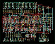
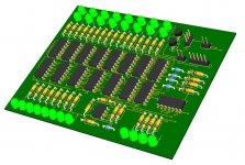
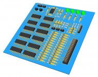
Attached Schematic, PCB layout, 3D view:
(The schematic is kinda messy....)
Instead of logging individual X states, it now counts the total number of trials and number of correct guesses.
During each trial, the user can switch between "A", "B", "X" and "Mute" then press "Guess A" or "Guess B".
Once the switch box receives an answer the "trial counter" goes up by 1 and the "correct guess" counter will also go up by 1 of the guess it correct.
Both counters range from 00 - 99, when counters are at 99 and a +1 signal is given, nothing will happen.
During any time in the test, the user can also press the "reset" button to reset the test.
because different people may need different relay configurations depending on their applications, relays are not included on-board, instead, 2 open-collector outputs are given for each of the states (A and B).
due to the variations in 7-segment display pinout, they are also located off-board, a 30-pin connector with V+ and 4x7=28 open-collector outputs is given...
On-board BOM:
An externally hosted image should be here but it was not working when we last tested it.
Off-board BOM:
n x audio I/O sockets
n x Relays
3 x SPST Push-Switch
1 x SP4T Rotary switch
4 x 7-Segment LED display
1 x DC power socket
EDIT:
The On-board BOM says that the 74HC32 is a NOR gate, it's actually an OR gate
Attached Schematic, PCB layout, 3D view:
(The schematic is kinda messy....)
Attachments
Last edited:
- Status
- Not open for further replies.
- Home
- Source & Line
- Analog Line Level
- Discrete Logic ABX Switch Box