Hello,
I'm in the concept phase of a preamp for my new amp which shall be finished in the next months. (https://www.diyaudio.com/forums/sol...low-nfb-fet-front-bjt-ops-13.html#post6043036)
As this amp has 29dB of gain, I'm not planning to add gain in the preamp as most sources have about 2vrms output. (don't now at the moment what a bluesound node 2I does, if anybody knows…)
I've found plenty of preamp circuits with gain (UGS, DCG3, Dennesen JC80, pumpkin,..., but discrete buffers are not that common. We all know the B1 from Nelson.
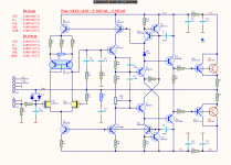
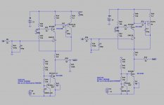
As I like to design/change/adapt circuits myself, based on proven designs and not copy existing stuff, I managed to get good performance out of the circuit below.
The power supply must be a really stiff one, as this circuit has loussy PSRR.
The Jung Didden supperreg seems pretty easy to build and looks ideal to me.
Any comment's on how to improve further? Lower noise? Lower output impedance…?
I'm in the concept phase of a preamp for my new amp which shall be finished in the next months. (https://www.diyaudio.com/forums/sol...low-nfb-fet-front-bjt-ops-13.html#post6043036)
As this amp has 29dB of gain, I'm not planning to add gain in the preamp as most sources have about 2vrms output. (don't now at the moment what a bluesound node 2I does, if anybody knows…)
I've found plenty of preamp circuits with gain (UGS, DCG3, Dennesen JC80, pumpkin,..., but discrete buffers are not that common. We all know the B1 from Nelson.
As I like to design/change/adapt circuits myself, based on proven designs and not copy existing stuff, I managed to get good performance out of the circuit below.
The power supply must be a really stiff one, as this circuit has loussy PSRR.
The Jung Didden supperreg seems pretty easy to build and looks ideal to me.
Any comment's on how to improve further? Lower noise? Lower output impedance…?
Attachments

Yeah, a cap to ground at both ends of R4 might improve the PSRR situation a fair bit... (I would also include maybe 330R worth of base stopper R for Q1 and Q9.) Actually, maybe the one at the upper end of R4 should go to the output instead for a bootstrap, then Vds would be kept ~constant.No capacitor at Q9 and Q1 bases?
Other than that, looks decent enough. Maybe 47-100 ohms worth of output series R, to keep off the evils of the world out there (including cable capacitance)? This is probably going to be less noisy than the power amp input anyway...
The current source down there seems rather more complex than what a follower would normally require. What's all this ZTX951 business?
Having super-duper regulators is all fine and dandy but I'd prefer to have enough PSRR to not need any (beyond, say, a low-noise LM317/337 pair) instead. Audio tends to leave many ways of accomplishing this. In the olden days, people used lots and lots of RC filtering - that worked, too...
I'm not exactly a fan of relying on obsolete semiconductors either. That said, the situation with JFETs isn't like it could be.
As this amp has 29dB of gain, I'm not planning to add gain in the preamp as most sources have about 2vrms output.
The most sources have comparatively low output impedance and can more or less successfully drive some kOhm load.
Why do you think you need a follower?
Hi,
In 2012 I started the thread preamp-buffers-simple-idea (see #52ff) which dealt with a very similar question to Yours.
It finally evolved to the still simple Calvin Buffer that shows an excellent signal behaviour.
Differences to Your circuit that You may find intersting are the cascoding of JFETs and a SEPP-style modulation of the current source.
The current capability of the JFETs is also vastly improved by utilizing bipolar PNPs in a Sziklai fashion.
With regard to Yor circuit, changing the cascode Q9 from constant to floating will improve THD considerably. This could be achieved by bootstrapping Q9´s base potential with the V(out) potential.
While paralleling J1 and J9 increases bias current and as such the load current capabilities, it will probabely still not be enough to drive lower impedance loads.
You could change the constant current source into a modulated-by-the-audio-signal-current source, thereby almost doubling load current capability and increasing efficiency considerably.
The power supply rails are imho way too high. I wouldn´t go above ~10V of Vds for the JFETs. Gate leakage almost explodes under high-voltage/high-current conditions and may lead to a fatal latch-up of teh JFETs.
With a floating or bootstrapped cascode You could increase the useable range from the supply rail as You can keep the Vds of the JFETs almost constant and low. 4-5V suffice for the 389s.
The cascode and the current source shield the JFETs from the supply rails, so PSRR isn´t too bad ..... if You decouple the base potentials with caps.
In my experience these very simple JFET Buffers require (oversized) large capacitance reservoires as close as possible to the JFETs to improve Bass response.
jsuu
Calvin
Last edited:

> this circuit has loussy PSRR.
How loussy?
Misspelling turns contagious 😀
I also wonder why a buffer is needed at all these days. In many cases your signal source have sufficient drive and level, loading of the power amp is minimal, thus the sources can drive the power amp just fine.
Can see gain being needed for some sources like for phono or older tape gear, maybe your cell phone and computer sources too.
Currently listening to a Yamaha T-85 tuner going through a stepped attenuator driving my new Hafler DH-220C design, sounds just fine to me. For normal listening levels, the attenuator is not far off its minimum setting.
Could see a pre-amp with multiple inputs, some having gain and many not needing any active circuitry in the signal path. To each there own YMMV
Last edited:
The power supply rails are imho way too high. I wouldn´t go above ~10V of Vds for the JFETs.
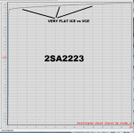
This might be an invitation to install a pair of capacitance multiplier circuits, one per rail. They would reduce supply ripple and noise by about 40 dB, thus increasing PSRR by about 40dB. They would also drop the 24V supply voltage to whatever value you wish, perhaps even ~10V as proposed above.
edit- Protip: for the series pass devices in the capacitance multiplier, choose transitors with very high "Early Voltage" (SPICE model parameter VA), thus very flat ICE versus VCE curves. The higher the Early Voltage the greater the attenuation.
_
Attachments
Last edited:
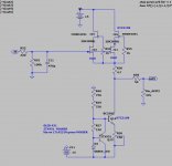
Or if you don't want to fool around with special high-Early-voltage transistors, just build your capacitance multipliers as cascode circuits, using any transistor types you happen to have lying around. ZTX851/951 {as seen in the OP} would be just fine. BD139/140 too. MJE340/350, MPS8099/8599, whatever.
Since you're dropping a bunch of volts across the capacitance multiplier (24V ---> 15V (?)) you've got plenty of headroom for the cascode.
Since you're dropping a bunch of volts across the capacitance multiplier (24V ---> 15V (?)) you've got plenty of headroom for the cascode.
> this circuit has loussy PSRR.
How loussy? -20dB? -60dB?
No capacitor at Q9 and Q1 bases?
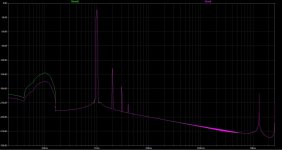
Don't know exactly how many dB, but see the FFT's below. I put a 100Hz sine voltage 0.3V amplitude in series with the PSU. The 100µF cap over R4 makes it 50dB better. (FFT picture is incl. cap)
Yeah, a cap to ground at both ends of R4 might improve the PSRR situation a fair bit... (I would also include maybe 330R worth of base stopper R for Q1 and Q9.) Actually, maybe the one at the upper end of R4 should go to the output instead for a bootstrap, then Vds would be kept ~constant.
Other than that, looks decent enough. Maybe 47-100 ohms worth of output series R, to keep off the evils of the world out there (including cable capacitance)? This is probably going to be less noisy than the power amp input anyway...
The current source down there seems rather more complex than what a follower would normally require. What's all this ZTX951 business?
Having super-duper regulators is all fine and dandy but I'd prefer to have enough PSRR to not need any (beyond, say, a low-noise LM317/337 pair) instead. Audio tends to leave many ways of accomplishing this. In the olden days, people used lots and lots of RC filtering - that worked, too...
I'm not exactly a fan of relying on obsolete semiconductors either. That said, the situation with JFETs isn't like it could be.
The most sources have comparatively low output impedance and can more or less successfully drive some kOhm load.
Why do you think you need a follower?
Thanks for the tips.
Bootstrap...well? I've never used it in any of my circuits.
The ZTX951 business: this is Walt Jung GLED431 project = voltage reference with 1/100 of noise compared to a TL431.
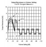
Well, the reason I would like to use a buffer is due to the MUSES72320 volume control I'm willing to use, the output resistance is dependant on the volume setting and has quite a big range 1k...6.5K, see picture out of datasheet below.
I've changed the fixed cascode to a floating one, FFT and THD is identical. Except for the phase angle's of the harmonics, but have no idea how important this difference is??
Hi,
In 2012 I started the thread preamp-buffers-simple-idea (see #52ff) which dealt with a very similar question to Yours.
It finally evolved to the still simple Calvin Buffer that shows an excellent signal behaviour.
Differences to Your circuit that You may find intersting are the cascoding of JFETs and a SEPP-style modulation of the current source.
The current capability of the JFETs is also vastly improved by utilizing bipolar PNPs in a Sziklai fashion.
With regard to Yor circuit, changing the cascode Q9 from constant to floating will improve THD considerably. This could be achieved by bootstrapping Q9´s base potential with the V(out) potential.
While paralleling J1 and J9 increases bias current and as such the load current capabilities, it will probabely still not be enough to drive lower impedance loads.
You could change the constant current source into a modulated-by-the-audio-signal-current source, thereby almost doubling load current capability and increasing efficiency considerably.
The power supply rails are imho way too high. I wouldn´t go above ~10V of Vds for the JFETs. Gate leakage almost explodes under high-voltage/high-current conditions and may lead to a fatal latch-up of teh JFETs.
With a floating or bootstrapped cascode You could increase the useable range from the supply rail as You can keep the Vds of the JFETs almost constant and low. 4-5V suffice for the 389s.
The cascode and the current source shield the JFETs from the supply rails, so PSRR isn´t too bad ..... if You decouple the base potentials with caps.
In my experience these very simple JFET Buffers require (oversized) large capacitance reservoires as close as possible to the JFETs to improve Bass response.
jsuu
Calvin
Thanks for pointing this out, will go through this thread.
Misspelling turns contagious 😀
Attachments

Last edited:
Yeah, a cap to ground at both ends of R4 might improve the PSRR situation a fair bit... (I would also include maybe 330R worth of base stopper R for Q1 and Q9.)
What is the reason you propose base stoppers here? Stability?
330R seems high for a base stopper?
Misspelling turns contagious 😀
"Loussy" is either "lousy" or "lossy" or both. I realized it does not matter, it is a useful word, English is a bastard language and we can make-up words by plan or by accident.
...see the FFT's below. I put a 100Hz sine voltage 0.3V amplitude in series with the PSU....
Looks like 0.03V on the sim plan. Which is about -30dB re:1V. The output is -148dB. That makes 128dB PSRR. That is very good for a "single stage". You can easily get better than 0.03V with a $1 regulator, maybe with added 100 Ohm + 1,000uFd R-C filter.
I would have to doubt ANY sim plotted down to -270dB. The real world is not that big. This is all "Fun with math".
There are simpler ways to buffer from >500k input to 50r output with buzz S/N and THD far lower than any recording studio. However I realize in DIY it is not always about "simple".
Hi,
In 2012 I started the thread preamp-buffers-simple-idea (see #52ff) which dealt with a very similar question to Yours.
It finally evolved to the still simple Calvin Buffer that shows an excellent signal behaviour.
While paralleling J1 and J9 increases bias current and as such the load current capabilities, it will probabely still not be enough to drive lower impedance loads.
In my experience these very simple JFET Buffers require (oversized) large capacitance reservoires as close as possible to the JFETs to improve Bass response.
jsuu
Calvin
Hi Calvin,
Wow, I saw your site, you have realized some very beautiful projects.
I will follow you experience regarding the simple jFET buffers and I'm already playing with an additional stage.
The purpose of the buffer is driving the 47k input impedance of my amp.
Attachments
Looks like 0.03V on the sim plan. Which is about -30dB re:1V. The output is -148dB. That makes 128dB PSRR. That is very good for a "single stage". You can easily get better than 0.03V with a $1 regulator, maybe with added 100 Ohm + 1,000uFd R-C filter.
I would have to doubt ANY sim plotted down to -270dB. The real world is not that big. This is all "Fun with math".
There are simpler ways to buffer from >500k input to 50r output with buzz S/N and THD far lower than any recording studio. However I realize in DIY it is not always about "simple".
Yes my bad, was 30mV! And thanks for the info.
Yes, I could use an opamp for this, but where is the fun in that? 🙂
Member
Joined 2009
Paid Member
I also wonder why a buffer is needed at all these days.
I have been wondering if the answer is “to drive a low impedance volume control potentiometer, as desired to minimize noise and maximize drive into the next cable/stage” ?
Hi,
thanks 😉 To convert the circuit in #16 to bootstrapping action simply disconnect C10 from gnd and connect it to either side of R35. C10, when charged up functions like a battery, so that the base voltage of the cascoding bipolar 'rides' on the output voltage.
Since the emitter follows the base by an almost constant Vbe the drain voltage of the JFet also 'rides' on the output voltage. The Drain-source voltage stays rather constant, varying much less than with a non-cascoded, or a fixed bias cascoded stage.
The beauty of using a second JFET (or other depletion mode devices like tubes) for the cascode besides its simplicity is that it performs the bootstrapping at the same, keeping the lower JFETs Vds almost constant. Thereby reducing the THD considerably.
For a 47k load this simple cascoded buffer should suffice.
If You intend to drive longer cable runs or generally lower load impedances the booster transistor aids in current capability. If the booster takes over most of the load current -say 80-90%- the current amplitude through the JFET is drastically reduced, so that it almost works under constant voltage, constant current conditions and hence with very low THD also into lower impedance loads
jauu
Calvin
Hi,
Have playing in spice quite a bit the last week.
The bootstrap showed indeed much better improvement than I first thought. Important is the capacitor value to get out of the audio frequency range regarding the RC time constant.
But have noticed that the jfet as cascode, and specially the 4391 gives very good results. I will highly probably first try this.
As I'd like to use both jfet's in the 2SK389BL device, I need two 4391 jfets to cope with the power dissipation. But noticed the very big range of cut off voltage 4...10V.
Has anybody (highly likely Calvin has) any idea about the spread of Vgs in the same batch. How many do I need to buy to find 4 identical ones?
Attachments
- Home
- Source & Line
- Analog Line Level
- Discrete buffers