Hi,
I wonder if anyone around here has ever attempted a discrete bridge tied load amplifier (single supply) or come across any good circuits.
Yeah, I know there are a lot of chip amps offering that, but I am interested in a discrete design instead. Especially if there is a class A version in the midst.
I would imagine trying to keep the output voltage of the two discrete amplifiers going to be a bit of a challenge.
I would reckon it would be a simple pushpull unity gain class AB amp at the output powered by a single common emitter amplifier. This is in turn fed by a simple phase splitter.
Any thoughts on this.
Oon
Last edited:
Hi, you can use virtually any stereo power amplifier, using a "bridging adapter" - something of this kind (although there may be many ways to implement such an adapter):
Bridging Adapter For Power Amps
Cheers,
Valery
Bridging Adapter For Power Amps
Cheers,
Valery
In Class A, this may be very similar a Circlotron or with headphone amps, often called “Balanced Drive”. For any of this to work, you need a source that has balanced output so that two phases of your input are generated from a single input. If you have a Preamp that has balanced outputs this is solved already. This can be done with two opamps or a monolithic SE to Balanced driver like one from THAT Corp. Or a special discrete SE Class A design using only two actives which has a very beautiful natural sound. With Class A “balanced drive” you can do this and avoid zero crossing distortion as ESP (Rod Elliot) warns about.
Advantages are double the slew rate and four times the power. It can really transform a headphone amp to make it balanced drive. I have actually done it with two SE Class A pocket amps, each stereo amp driving one can.
I don’t see why it won’t work for speakers. If amp is not AC cap coupled - care has to be taken to get a null DC offset or else voice coil will be offset to one side and burn off power even with no music. Same as any amp.
New Portable Amp - "Pocket Class A" by xrk971 - now available as complete PCB | Page 17 | Headphone Reviews and Discussion - Head-Fi.org
Here is proof of concept test with two SE to Bal driver boards powering two pocket Class A amps.
Last edited:
Here is the link to the Pass DIY Circlotron Class A amp.
Build The Amazing FET Circlotron | Pass DIY
Build The Amazing FET Circlotron | Pass DIY
It´s been done since forever but not as simple as you envision because a single phase splitter straight driving 2 unity gain "current gain" stages will need to swing rail to rail, not easy.Hi,
I wonder if anyone around here has ever attempted a discrete bridge tied load amplifier (single supply) or come across any good circuits.
Yeah, I know there are a lot of chip amps offering that, but I am interested in a discrete design instead. Especially if there is a class A version in the midst.
I would imagine trying to keep the output voltage of the two discrete amplifiers going to be a bit of a challenge.
I would reckon it would be a simple pushpull unity gain class AB amp at the output powered by a single common emitter amplifier. This is in turn fed by a simple phase splitter.
It´s done insted by using the phase splitter to drive 2 *full* power amps, with their outputs bridge wired to load, speakers or otherwise.
In the old days I used to commecially make a small unit called, not by chance, "The Bridger" , both self contained and as a spare add-on board, to turn commercial stereo amps into "bridged powerhouses 😀 "
Helped many friends turn Mom´s Akai or Sansui 40W per channel home amp into a fire breathing 80W into 8 ohm monster 😛 , ready to instill fear and Death into a single Guitar (or Bass) speaker inside a homemade (or recycled) cabinet 😀
Thanks for the inputs so far. I reckon to generate the two differential input, I will just use a transistor and 2 resistors. The amp I am looking at might be a simple class a comprising of a common emmiter with 3 diodes driving two transistor in push pull.
However I am planning to run it from single rail supply. So I wonder how do I keep the bias to both sides in check through different voltages, temperatures etc. I think those chips solve it by using a common bias voltage divider. Any other tips of these designs would be really helpful to me.
Thanks
Oon
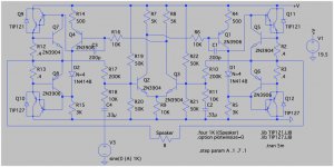
There's an example of a bone simple "native" BTL discrete design in the Educational directory that comes with LTSpice. PowerAmp.asc. Check it out.
Hey thanks,There's an example of a bone simple "native" BTL discrete design in the Educational directory that comes with LTSpice. PowerAmp.asc. Check it out.
I don't happen to have access to the LTspice. Any chance you could post the circuit here?
Oon
Here is the PowerAmp schematic from LTSpice examples.
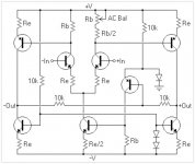
However, for practical use, this kind of circuit normally requires a common mode control loop (CMCL) - a simple implementation is shown at the 2-nd picture.
However, for practical use, this kind of circuit normally requires a common mode control loop (CMCL) - a simple implementation is shown at the 2-nd picture.
Attachments
Thanks, I think I figured out 2/3 of the circuit, will need a bit more to digest the rest...
Oon
Oon
- Status
- Not open for further replies.
- Home
- Amplifiers
- Solid State
- Discrete Bridge tied Load (BTL)