I am reading lots of positive things about CCS supply for DHT heaters, and therefore tested the attached schematic in Multisim. It ought to be a Voltage Controlled CCS. In theory it works, but how well? How can one calculate/determine how many volts the Mosfet needs for good functioning? Is that value related to Rds?
For testing purposes I included a 2VRMS source in series with the 12VDC source, and there was only some microvolts across the 7R resistor, but I don’t know if that is a valid test? I am curious about your opinions, also regarding stabilization, etc.
Regarding CCS usage in general. I am seeing that more and more people are using CCS’s to isolate the noisy PSU from the amplifying circuit. There are different heater/cathode circuits around, Richard Sears uses CCSs to feed Single Ended amplifiers and he refers to Kevin Carter using CCS in a fully differential PP amplifiers to eliminate current loops through the PSU. And Allen Wright (RIP) last amplifier had a fully diffential output stage as well.
Attachments
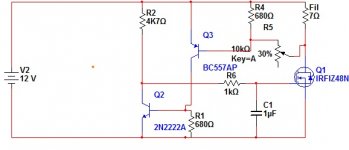
It's a constant voltage source with a terrible tempco, awful compensation, and no protection (from excessive current or voltage). It's also not a VCCS, because it doesn't show an input node which sets current.
The only reason it may seem to work is the 1uF on the gate (which will probably cause it to oscillate in practice; a simulation probably won't catch this).
This is a true VCCS and will do an excellent job:
Typically, Rg = 100 ohms, C = 100pF (optionally with a 4.7k resistor in series), R = 10k. To save on power dissipation and dropout voltage, choose a small Rs. For filament regulation purposes, you'll want a constant voltage on the input, which can be supplied from a voltage divider from a TL431 or something like that.
Note that parallel filaments are not strictly constant current in this method. You'd have to have a series chain for that.
A much better filament power source, for paralleled filaments, would be a current limited voltage regulator, preferably a switching regulator so you don't waste power.
Tim
The only reason it may seem to work is the 1uF on the gate (which will probably cause it to oscillate in practice; a simulation probably won't catch this).
This is a true VCCS and will do an excellent job:
An externally hosted image should be here but it was not working when we last tested it.
Typically, Rg = 100 ohms, C = 100pF (optionally with a 4.7k resistor in series), R = 10k. To save on power dissipation and dropout voltage, choose a small Rs. For filament regulation purposes, you'll want a constant voltage on the input, which can be supplied from a voltage divider from a TL431 or something like that.
Note that parallel filaments are not strictly constant current in this method. You'd have to have a series chain for that.
A much better filament power source, for paralleled filaments, would be a current limited voltage regulator, preferably a switching regulator so you don't waste power.
Tim
- Status
- Not open for further replies.