This is a question really for someone who has thoroughly gone thru this paper. It is a very detailed question. Not something which would invalidate any conclusion. I think it is an error. Strangely enough, Augspurger has published an update for this paper. But in this update he has copied the tables and figures verbatim.
My question is just out of interest, my speaker design does not depend on it, and perhaps no one would care.
The problem is in this table:

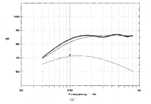
And this is fig 8a:

Augspurger uses a driver with Fs = 50 Hz for this.
According to the table Fs/Fp = 0.5 => Fp=Fs/0.5 = 100 Hz
F3/Fp=1 so F3 should be 100 Hz.
This is also what the table says, and completely in accordance.
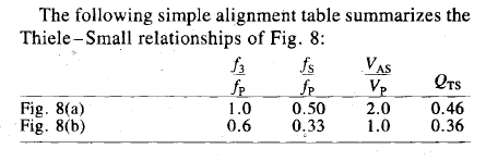
But now for Fig 8b he changes the tuning of the pipe, and the resulting response should
be according to this figure:

Table: Fs/Fp = 0.33 => Fp = Fs/0.33 => Fp = 150 Hz
F3/Fp = 0.6 => F3 = Fp * 0.6 = 90 Hz
This is completely off.
It would be strange anyway, when the Fp is increased, F3 would decrease.
From the figure, it looks more like F3 = 60 Hz
I have modeled the first case in Hornresp, using Fs and Qts from the table, using
average values for a 4" driver for the unkown values. I know this is very vague but I did not
have any other information.
The outcome of Hornresp was totally comparable, differing only in some magnitudes of
peaks and minima. All frequencies and curve shape were spot on.
Then, when doing the same for Fig 8b from the table, the Hornresp result did not even
resemble anything. Until I changed Fs/Fp to 0.66 instead of Fs/Fp and then the curves
matched almost.
So, is this an error in this paper? Given the counter-intuitive increase of Fp resulting in
a decrease of F3. And in Table 1 of the same paper the author also decreases Fp for a
decrasing Fs.
But then again, this was a published and peer-reviewed article and has been cited for 24 years.
jlinkels
My question is just out of interest, my speaker design does not depend on it, and perhaps no one would care.
The problem is in this table:
And this is fig 8a:
Augspurger uses a driver with Fs = 50 Hz for this.
According to the table Fs/Fp = 0.5 => Fp=Fs/0.5 = 100 Hz
F3/Fp=1 so F3 should be 100 Hz.
This is also what the table says, and completely in accordance.
But now for Fig 8b he changes the tuning of the pipe, and the resulting response should
be according to this figure:
Table: Fs/Fp = 0.33 => Fp = Fs/0.33 => Fp = 150 Hz
F3/Fp = 0.6 => F3 = Fp * 0.6 = 90 Hz
This is completely off.
It would be strange anyway, when the Fp is increased, F3 would decrease.
From the figure, it looks more like F3 = 60 Hz
I have modeled the first case in Hornresp, using Fs and Qts from the table, using
average values for a 4" driver for the unkown values. I know this is very vague but I did not
have any other information.
The outcome of Hornresp was totally comparable, differing only in some magnitudes of
peaks and minima. All frequencies and curve shape were spot on.
Then, when doing the same for Fig 8b from the table, the Hornresp result did not even
resemble anything. Until I changed Fs/Fp to 0.66 instead of Fs/Fp and then the curves
matched almost.
So, is this an error in this paper? Given the counter-intuitive increase of Fp resulting in
a decrease of F3. And in Table 1 of the same paper the author also decreases Fp for a
decrasing Fs.
But then again, this was a published and peer-reviewed article and has been cited for 24 years.
jlinkels
Attachments

As I recall, there were a couple of typographical errors in the AES paper, of which that was the main example. I'm not on my desktop machine at the moment, so I don't know off-hand whether it was corrected in George's subsequent 3-part Speaker Builder series of articles. However, it wasn't really part of the alignment tables (Tables 1 & 2 respectively) 'proper', which he later expanded on in his SB articles, particularly by including a set of those extended system alignments.
It was prettier to look at, & George extended his main alignment table to include what he described as the Extended System Alignments previously only touched on (with typo) in the short table accompanying Figure 8a & b. That was about it though, as you say, & the tables were still fairly sketchy, although you can interpolate from them, as d'Appolito did for his baseline Thor calculation before abandoning the Vp calculation as excessively large for Seas's requirements. In fairness, it does work, if you're after the near-aperiodic alignments he was targeting. His measurements on different damping materials are still about the best easily accessible in the context of QW pipes, and his modelling software wasn't too bad either -not as flexible as some, but reasonably so. I still use it sometimes.
Wow, I did not expect such fast reactions or even that people had studied that paper in depth. Thank you so much.
@planet10 : The article that you included in your thread is the version of article I have. With the error included. There is an updated version around on the internet: https://pdfcoffee.com/transmission-lines-updated-part-1-pdf-free.html
But it also included those errors. The tables and pictures were literally pasted in that update and I did not rate the update very high.
@Scottmoose : Agreed, the alignment tables at the end of the document seem to be correct.
I have not built a TL based on one the design rules of Augspurger so I cannot assess the quality. What struck me was how easily it is possible to simulate a TL in Hornresp with a satisfactory performance using these rules. And this paper also states weight/volume for various damping matrials, something which I could not find easily on the internet. The correlation between the amount of damping material as shown by Hornresp for a satisfactory response and the recommended amounts in Augspurger's paper is amazing. Yes, I know, it is only model calculation, but still.
I have not tried or used MJK sheets. I don't have Mathcad experience and I am a Linux-only user. I never tried Wine or alternatives. Hornresp runs in Wine.
jlinkels
Oh, George's work was excellent. The paper / articles and limited alignment tables were very good within the context they were targeting (essentially near-aperiodic TLs) and his software wasn't bad at all as it offered much more freedom than the tables. And as noted, his work on damping, particularly the varying behavior of different materials, is still very useful. The SB articles weren't really updates per se, beyond expanding the alignment tables proper in part 3: it was more about access & publicity for what was (and still remains) a much-misunderstood field. Most SB readers around the turn of the century will not have been AES members, or likely to have been regularly stumping up for access to individual papers, even from a heavyweight name like George, so having the data presented again in a more available form will have been very useful. Ironically, these days SB has long-gone & it's the AES original that's the more easily accessible for many.
Martin's work was complimentary, and as far as geometry etc. went was / is rather more flexible, if a bit more limited in terms of damping material characteristics. Swings & roundabouts, though overall Martin's wins out for its ability to model more complex forms. I use both, along with a bunch of others when necessary like Hornresp, Akabak & some of my own.
Martin's work was complimentary, and as far as geometry etc. went was / is rather more flexible, if a bit more limited in terms of damping material characteristics. Swings & roundabouts, though overall Martin's wins out for its ability to model more complex forms. I use both, along with a bunch of others when necessary like Hornresp, Akabak & some of my own.
- Home
- Loudspeakers
- Full Range
- Discrepancy in Augspurger paper on Loudspeaker on Damped Pipes?