I've "upgraded" my 6B4G amp, a completely modded ST-70, to accept 300B tubes interchangeably. It uses the stock Dynaco transformers, the original choke in the power supply and the chassis. The driver board is a Curcio "premium" board that is spec'ed to use 4x6DJ8 as phase splitter/LTP, but I've been using 6N6P instead in the driver position. The main change with the power tubes is to remove the negative fixed bias and use cathode bias with 550R on the filament center tap. I also disconnected the negative feedback. Of course the UL tap just dead ends at the tube socket since the pin is open on a 6B4G. It really isn't hard to do the mod and make it work. The quad cap was replaced with a Curcio board that increases the capacitance with higher voltage caps and also nicely has bleeder resistors built in.
With the 6B4G tubes this amp just rocks, and can also play the soft stuff with finesse. I really had no complaints with it. And it has been stable too, no problems with it.
I modded it for 300B by removing the old unused cathode ground and the 10R resistor for the bias measurement. (the original I believe is 15.6R but you can't find them.) I then ran dropping resistors between pins 2&1 and 7&8. I wired adapters to take the heater voltage from 1&8 whereas the 6B4G uses 2&7. Each side worked when I tried it. So far, so good.
But what happens with the 300B in place is that when I turn up the volume one side drops out and doesn't come back when I turn it down. And not that loud either, just moderate really. (It is playing a lot louder than that now, We Will, We Will Rock You!!! So loud, but with the 6B4G). The PS is shared, so it isn't that. I have 2 theories. First, I don't have enough current to power both sides and one just drops. Second, the dropping resistors can't take the current through them. When I turn it off and back on both channels will play. And the 6B4G continue to work as always, so I haven't fried anything important. I haven't tried switching sides with the tubes but I'll do that tomorrow.
I'm also disappointed with the bass, but if I can't turn it up I won't get much bass anyway.
Any ideas? I get that I'm stretching an ST-70 beyond its limits so maybe I should just leave well enough alone and build a real amp.
I suspect blocking distortion... This would say your bias point is off, and you're driving the 300B grid positive.
I'm only getting 50v on the cathode, and my understanding is that the 6N6P can swing 75v. Would that be it?
What would I do to correct that?
What would I do to correct that?
I'm only getting 50v on the cathode, and my understanding is that the 6N6P can swing 75v. Would that be it?
What would I do to correct that?
That depends on a lot of things... I'd need to see a schematic to tell...
My VA/PI/VA design will swing over 150V but it uses almost 600V B+ to do it 🙂
I'd have to measure all the voltages. I've already had a few glasses of wine tonight, so I'll check tomorrow. I had measured 420v at pin 2, and 4.95vac at 1-4 for filament voltage, and 50v at the center tap of the filament. That was with only one side though, maybe it was lower when I put both sides together.
As far as schematics go, there isn't one overall schematic since it was one mod over another over another. I could probably draw one up but it'll take some time.
As far as schematics go, there isn't one overall schematic since it was one mod over another over another. I could probably draw one up but it'll take some time.
Last edited:
See below for measurements.
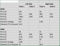
I first measured with the Sovtek 6B4G in place and everything seemed as I remembered, and this is working fine. I then measured with 300B in place. The only difference in the circuit other than the tubes themselves are the two .27ohm dropping resistors on the filaments, one on each leg per side.
I also noted that on one side at least the plate voltage coming from the output transformer isn't quite balanced. The other is OK. Also, the filament voltages are low for the 6B4G, but they were too high before I put a third .27ohm resistor on one leg on each side. Which is worse, too high or too low?
It looks to me like the bias voltage is too low and the grid would go positive with only a little push. The bias comes from 4x2200R/5w resistors on the center tap of the filament, without a bypass cap. No hum pot or anything else.
What can I do to make this work, without adding any complexity? I know a schematic would be helpful but I don't have one. I'll try to draw one up of the power section.
Listening after testing sounded pretty good but very laid back.
Attachments
Why wouldn't you use a bypass cap? Absolutely put one on there.
Is that 550 ohms for the quad of tubes, or two 1.1K loads split between each pair of output tubes? Since your left and right side bias voltages are different, I would guess you have two separate pairs of biasing resistors.
Your 300Bs would then be operating very anemically. 38V across 1.1K is 34mA per pair of tubes. That's less than half of what I would run. If you can put a fixed bias supply back into the design, it would be great to use that whole 400V rail that you have, otherwise you would want about 500 ohms of cathode bias resistance per pair of 300Bs to get them motivated to conduct a little more.
I am not surprised you don't like the way this sounds.
It's 550 ohms per pair so it isn't that anemic, but I'd still think it is low.
There is a bias supply with a bias pot that was disconnected from the driver when this was converted to cathode bias. This was an ST-70 at one point, so whatever bias voltage it used is still available.
There is a bias supply with a bias pot that was disconnected from the driver when this was converted to cathode bias. This was an ST-70 at one point, so whatever bias voltage it used is still available.
Yeah, 38V across 550 ohms is still only 34mA per tube. You'd really want to get to 50mA at least.
How do I increase the current then with cathode bias? Do I increase or decrease resistance? I've seen schematics with it both higher and lower.
With 400V of B+ and a 4.3K OT, I would want to run 90mA of current to end up with about 330V on the plate and -60V of bias. You can't do that though because the PA-060 will melt if you draw that much current through it. If you have the newer PA-060 with the taller stack, that would be good info to have.
The 55V bias tap on the PA-060 doesn't quite have enough juice to generate the desired negative bias rail that you'd want. You'd want about -90V of bias so you could dial in the 300Bs to run at about 50mA each (again assuming the newer PA-060). You could use the PA-060 bias rail to generate about -85V, then use a 50 ohm cathode bias resistor common to each pair of 300Bs. Heck, since this is so experimental anyway, take out the factory bias pots and put in a pair of 100 ohm 5W pots wired as variable resistors, then use them to set the idle current.
After writing all this, you have convinced me that the ST-70 is better off being used with 6B4Gs.
Unfortunately this is an older ST-70. With the 6B4G in place the transformer is only slightly warm. Would it be worth buying a drop in replacement that has higher ratings?
The bias pots aren't original, but I don't know the rating offhand. I'll have to open it up again.
If I can't make this work, maybe it'll be time to put those Lundahl transformers to use and build a real amp. I have a pair of LL1544A and a pair of LL1692A just waiting. Maybe get a bigger power transformer too and go from there, starting with an Amity type amp.
I should add that in the meantime, it still sounds great with the 6B4G. It is much better sounding than the EL34, even with a lot less power.
Last edited:
Having build both SE and PP 300B amplifiers, here is what I did:
a) In PP, think of the two 300B's as "mirrored" - so the 300Bs run back to back so to speak
b) Therefore: we can view each 300B as a class A amp output stage
c) At 420V or so of B+, we would use a 1K - 20W bias resistor to get ~80mA BIAS current
d) So here is what I did: DC on the heaters and the two 300B heaters tied together (back to back ) so pin 3-A to pin 3-B and pin 4-A to pin 4-B (the fat pins on each tube connected to the same pin on the other)
e) Now run 5V DC on the heaters
f) Now connect a 1K 20W resistor to pin-pair 3AB and another to pin-pair 4AB - both goes to GND - 0V. This way the two 1K resistors effectively work in parallel with is what we want for 2X~80mA = 160mA of bias current.
g) Here is the trick: you don't need a bypass cap on each "leg" because the phase on the cathode is 180 degrees out of phase.
h) If you really really want, you can place 2 100uF-100V across the two 1K cathode resistors - but liked the self-balancing effect of not having these.
i) Finally, use a scope to see of your driver tube can swing the 80V AC signal you need to run the 300B's to full swing. If not, you may have to redesign that...
If all goes well, you now have a killer 18W PP 300B amp.
Good luck!
http://www.bonavolta.ch/hobby/images/audio/300bpp_1.gif
The back-to-back 300B output stage is certainly not new. Worked for movie theaters back in the 30's
D.
The back-to-back 300B output stage is certainly not new. Worked for movie theaters back in the 30's
D.
Thanks but I'm trying to work with what I have.
This just isn't making sense to me. I'll try doing something with the cathode resistors, but I doubt I have any values in high wattages. I can easily enough go from 4x2200 to 3x2200 so I'd have 733R. I'll try it and see what I get. I don't think I'll get what I want though.
This just isn't making sense to me. I'll try doing something with the cathode resistors, but I doubt I have any values in high wattages. I can easily enough go from 4x2200 to 3x2200 so I'd have 733R. I'll try it and see what I get. I don't think I'll get what I want though.
I can easily enough go from 4x2200 to 3x2200 so I'd have 733R. I'll try it and see what I get. I don't think I'll get what I want though.
I did some ltspice 300B PP simulations (one channel only):
@400V plate with different cathode resistances.
The limitation (and many others) of pxmfr PA-06 is not modelled.
R V(cathode to ground) I(cathode resistor)
1K 72 72mA
800 70 87mA
440 63 144mA
The trend is lowering R yields lower voltage but higher current.
So your 50V with 1K is out of the norm.
It also occurs to me that the filament/heater current requirements:
EL34 (1.5A) > 300B > 6B4G (1A)
6N6P >> 7199 > 6DJ8
When you turns up the volume, one side shuts off ...
what are the filament currents going to the 300Bs at that point ?
- Home
- Amplifiers
- Tubes / Valves
- Disappointed with my 300B PP build