After lurking for a bit a looking at lots of designs, I've started cobbling together my own.
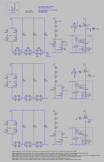
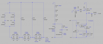
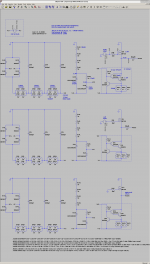
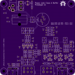
This is a class A buffer for low-voltage headphones, with no input or output capacitors (similar to the directly coupled B1 buffers in this forum).
This is intended to drive my Etymotics, which only need about 0.2V.
There are three "channels": right, left, and a virtual ground return.
The source follower is an IRF510, and the constant-current sink is my tweak on something jerluwoo posted in https://www.diyaudio.com/forums/sol...ource-ccs-audio-applications-post4785961.html
It seems to simulate fairly well 🙂
Haven't actually built it yet, that's next 😀
This is my first "real" attempt at making an amp, so any and all feedback is welcome!
Attachments
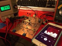
Holy lead inductance batman, a while prototype appears!
I put together a prototype with 2N7000, P2N2222, targeting 100mA bias current. It works! I did chicken out and use caps on the input though 😛
Next I need to learn how to do distortion measurements. 😀
I put together a prototype with 2N7000, P2N2222, targeting 100mA bias current. It works! I did chicken out and use caps on the input though 😛
Next I need to learn how to do distortion measurements. 😀
Attachments

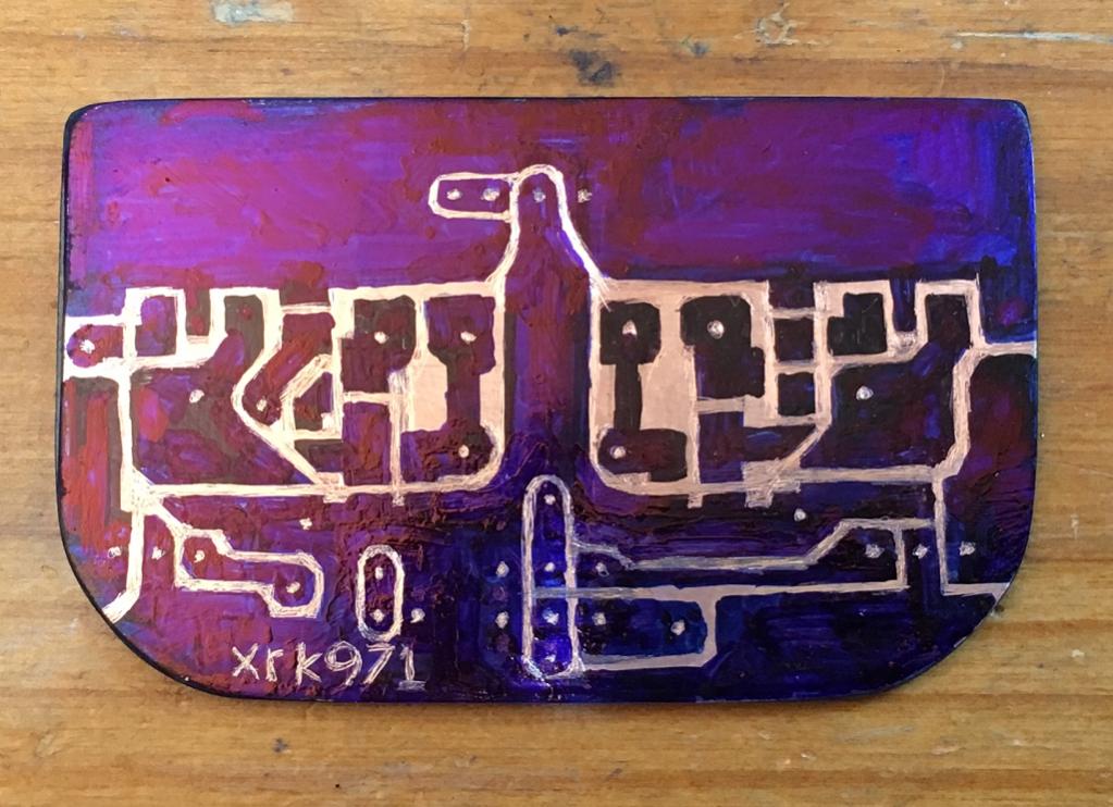
That’s a different way to make P2P. Stacked layers for voltage rails is a great idea.
Using a Sharpie marker and axis etch is very easy too. I did that for several amps and they worked well. The PCA original prototype was made that way.

Using a Sharpie marker and axis etch is very easy too. I did that for several amps and they worked well. The PCA original prototype was made that way.
Very cool xrk! I didn't know about the sharpie trick.
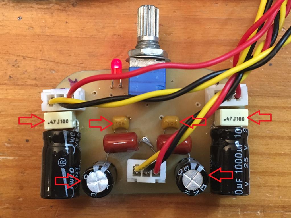
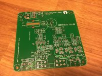
I threw together a PCB design with some extra footprints and test points for experimentation. Should be here in a week, I'll report back!
edit: derp, I put the LED in backwards. oh well 🙂
edit 2: I should also note that this design absolutely requires a "floating" power supply. if the negative terminal of your power supply is directly connected to ground, it will not work.
Attachments
Last edited:
You missed the opportunity to also put your GitHub link in the silkscreen as a QR Code, there would have been plenty space. 😉
But gotta love OshPark, their boards always look beautiful and I never had the slightest problem with PCBs from them.
But gotta love OshPark, their boards always look beautiful and I never had the slightest problem with PCBs from them.
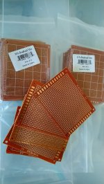
I use these prototyping boards. Cheap from China. Do not overheat them, copper will separate from the substrate. You get what you pay for 🙂
But they work for quick and dirty test work. No need for etching. You can get them online or I found out that MicroCenter now stocks lots of useful electro parts, just like RadioShack used to.
But they work for quick and dirty test work. No need for etching. You can get them online or I found out that MicroCenter now stocks lots of useful electro parts, just like RadioShack used to.
Attachments
Ah, MicroCenter brings back memories! I grew up in Houston and loved to browse there. Good to hear they are stocking some components.
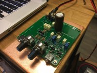
Welp, the boards arrived. Unfortunately they have a buzz problem. 😱
When I have the laptop plugged into the wall, the amp is picking up buzzing noise. This noise is affected by moving around the mouse.
If I unplug the laptop from the wall, the buzz completely disappears.
The puzzling thing is, my copper clad prototype was completely free from this problem.
I tried placing a piece of copper clad beneath the PCB (soldered to power supply negative), but it had no effect.
I tried switching from directly connected input to 1uF film caps, but it didn't affect the buzzing.
Very interesting, time to debug! 😱
Attachments
I wonder how accurate the -4.6V at the output is between all three sections. What is the voltage difference between the 'ground return' section and the two active sections? That is not shown on the sim.
It may be OK in the sim (all same name devices are identical in a sim but not in reality), but I wonder how it works in real life. Did you measure that?
Nice PCB layout BTW.
Jan
It may be OK in the sim (all same name devices are identical in a sim but not in reality), but I wonder how it works in real life. Did you measure that?
Nice PCB layout BTW.
Jan
Last edited:
Hi Jan, thanks for the kind words!
Yes, it is critical to adjust the output offset of both channels to zero (or within a few millivolts), using the 10-turn potentiometers.
With the PCB version of the buffer, I actually did not "match" any of the 2N7000's while assembling the board, and I had to fudge around with the current sense and trim resistors a bit (I dialed one of the 10-turns all the way and it wasn't quite enough, oops!). This is why you can see a few of those resistors sticking up so high off the board.
Hmm, I made a mistake with the R26 and R27 1meg input capacitor drain resistors. I should not have tied them to the sleeve, as that makes it impossible to galvanically isolate the amp from the input, if you choose to use input capacitors (and omit the R28 10k ground-tie).
Ok, I figured it out.
The "ground link" resistor (which joins audio ground to buffer "positive" rail) was too high in value. Lowering it to 1k reduced the buzz volume, and lowering it to 100R reduced the buzz beneath the level of my tinnitus. Of course, a dead short also eliminates the buzz.
I must admit I chose 10k as a "I'm not sure about what I'm doing" value. And also in case someone decided to use a non-floating power supply (which would feed 5 volts back into your DAC ground).
What surprises me was that something else I tried earlier did not fix the buzz: I modified the circuit such that the buffer circuit was galvanically isolated from the audio input:
surprisingly, the buzz persisted past this "isolated" version.
The "ground link" resistor (which joins audio ground to buffer "positive" rail) was too high in value. Lowering it to 1k reduced the buzz volume, and lowering it to 100R reduced the buzz beneath the level of my tinnitus. Of course, a dead short also eliminates the buzz.
I must admit I chose 10k as a "I'm not sure about what I'm doing" value. And also in case someone decided to use a non-floating power supply (which would feed 5 volts back into your DAC ground).
What surprises me was that something else I tried earlier did not fix the buzz: I modified the circuit such that the buffer circuit was galvanically isolated from the audio input:
- populate the input capacitors C3, C4
- remove (open circuit) the "ground-link" resistor R28
- remove the cap drain resistors R26, R27
- rig two new cap drain resistors, 1meg from TP14 to TP18, and 1meg from TP16 to TP22
surprisingly, the buzz persisted past this "isolated" version.
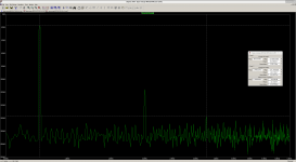
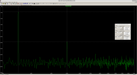
The next step will be to do some distortion analysis. I have ordered vicnic's 1kHz ultra-low distortion oscillator, which should arrive soon. Excited! 😀
 -- Very pretty board!
'Floating supply' always seems like a much better idea than it turns out in practice -- you still need a return path for the input signal .. but, then, you've already discovered that. 😉
The input signal could be referred to Vg in the original schematic. But that would make it more vulnerable to connection mishaps.
100mA still seems a little heavy for TO-92 devices -- they're gonna get pretty toasty dissipating around half a watt each quiescent.
Cheers
Thanks Rick!
The circuit is currently running off of 5.0 volts, with about 2.7 of that across the fets. So the to-92’s are dissipating about a quarter watt each.
The circuit is currently running off of 5.0 volts, with about 2.7 of that across the fets. So the to-92’s are dissipating about a quarter watt each.
- Home
- Amplifiers
- Headphone Systems
- directly coupled class A buffer for low-voltage headphones (work-in-progress)