The software is developed by member kimmosto and you are right it is awesome! very powerful for all kinds of experiments and also for actual loudspeaker design and crossover work!
You could do the same with a side by side arrangement.Hi Rob, stacking vertically will not be possible with a 2-way design. I would need to cross the lower woofer at a much lower frequency (max 200hz) to avoid serious lobing because of the greater distance to the mid horn.
https://www.google.com/url?sa=t&rct...s-pdf.61341/&usg=AOvVaw03_1kMtu3l_w0HVulEYlum
Have you worked out how much?Hi Rob, stacking vertically will not be possible with a 2-way design. I would need to cross the lower woofer at a much lower frequency (max 200hz) to avoid serious lobing because of the greater distance to the mid horn.
Yes I also had the Everest in mind!
But aren't the 15" angled outwards, away from eachother? Or is it an optical illusion on that photo? That would intuitively seem wrong, considering the earlier mentioned Kinoshita monitors have the woofers angled inwards to counteract lobing.
But aren't the 15" angled outwards, away from eachother? Or is it an optical illusion on that photo? That would intuitively seem wrong, considering the earlier mentioned Kinoshita monitors have the woofers angled inwards to counteract lobing.
Have you worked out how much?
Well if we consider a center to center distance of 40cm between the two vertical woofers, and going by the 1/4WL rule, the frequency where they stop acting like a single point source is almost exactly 200hz and up.
I don't know how much this rule can be stretched without introducing audible lobing issues.
Outward makes more sense.
It would be very helpful if you backed up your statement with an explanation, since it is quite obvious I don't understand this 🙂
What would be the spacing of the waveguide from the top woofer, and its vertical angle?Well if we consider a center to center distance of 40cm between the two vertical woofers, and going by the 1/4WL rule,
Quarter wavelength isn't a rule, even though it provides unique properties.
Not so obvious, how about this...It would be very helpful if you backed up your statement with an explanation, since it is quite obvious I don't understand this 🙂
Attachments
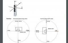
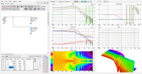
^ that is very intuitive and easy to think how it should work, but the data seems to indicate toe in works better in terms of easier integration to a horn. Unless I'm interpreting the simulation wrong, positive angle on right driver (that has positive X offset to the reference axis) should rotate it outwards and it looks like it but I'm second guessing because it feels like against intuition 😀 Anyway project file, diffraction simulation and the resulting measurements attached if someone wants to play with it.
Here is another set, the attachments are
1. baffle sim whose response loaded to the drivers, both use the same
2. toe in - rotation 22 degrees inwards per driver
3. toe out - rotation 22 degrees outwards
4. toe in - rotation 45 degrees inwards per driver
5. toe out - rotation 45 degrees outwards
6. coordinate system
and the project ZIP.
edit. thinking of it the toe out responses are probably closer to real than the toe in where the drivers would obstruct each other a bit causing interference.
Noticed the 22 degree samples have bit smaller X offsets but that doesn't make much difference at all.
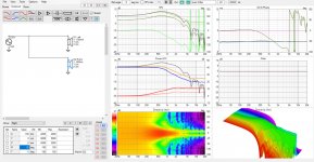
Attachments
Last edited:
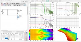
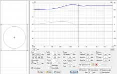
Actually there is some difference due to smaller X offset! When c-c is 360mm (180mm and -180mm on the drivers) the side lobes are not so pronounced around 1kHz. But increasing the spacing to 400mm nominal 90 degree pattern goes lower. The other has 90 nominal horizontal dispersion around 550Hz and the other around 470Hz.
If the 400mm wide test baffles were right against each other side by side flat, c-c would be 400mm. Rotate both about 22 degrees either way and the c-c becomes smaller, to about 370mm (if calculated using trigonometry and not just approximated 🙂. Or does it stay at 400mm on toe out situation, measured around the corner?😀 Too late evening for serious thought.
Attached GIF shows toe in situation with 22 degree rotation on both drivers. c-c spacing is varied between 360mm and 400mm. The polar map is normalized to give good look on the pattern.
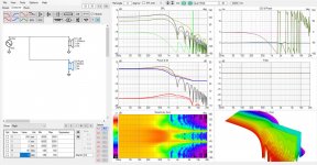
It is interesting to observe there is flat DI above ~1kHz in the toe in situation which can be increased or lowered by changing the rotation angle of drivers. Optimal angle seems to be somewhere between 10 - 35degrees perhaps, depending on what kind of horn there is to integrate with. Less rotation makes the pattern very narrow. More rotation and the patterns seem to get too wide and dirty. Less c-c seems smoother on the lobing sector but more spacing gives pattern control to lower frequency.
I suggest anyone considering such system to play with the simulation, it is very interesting to see what happens when parameters get manipulated and try to get a good balance 🙂
if xo to a horn was somewere around 400-500hz the stuff above 1khz doesnt matter that much.
If the 400mm wide test baffles were right against each other side by side flat, c-c would be 400mm. Rotate both about 22 degrees either way and the c-c becomes smaller, to about 370mm (if calculated using trigonometry and not just approximated 🙂. Or does it stay at 400mm on toe out situation, measured around the corner?😀 Too late evening for serious thought.
Attached GIF shows toe in situation with 22 degree rotation on both drivers. c-c spacing is varied between 360mm and 400mm. The polar map is normalized to give good look on the pattern.
It is interesting to observe there is flat DI above ~1kHz in the toe in situation which can be increased or lowered by changing the rotation angle of drivers. Optimal angle seems to be somewhere between 10 - 35degrees perhaps, depending on what kind of horn there is to integrate with. Less rotation makes the pattern very narrow. More rotation and the patterns seem to get too wide and dirty. Less c-c seems smoother on the lobing sector but more spacing gives pattern control to lower frequency.
I suggest anyone considering such system to play with the simulation, it is very interesting to see what happens when parameters get manipulated and try to get a good balance 🙂
if xo to a horn was somewere around 400-500hz the stuff above 1khz doesnt matter that much.
Attachments
Last edited:
Edit time over. looking back the toe out situation the patter control seems way more effective below the ~500hz than with toe in. Maybe it was better option in real application after all, especially with very large horn with narrow pattern, and a steep xo 🙂... toe in still looks easier to integrate though.
Last edited:
It would be possible. The drawing shows a simplified aspect of the situation, which is helpful if you understand how to interpret it. VituixCad also works with certain simplifications and assumptions, which is fine, but you need to know how to interpret it.Unless I'm interpreting the simulation wrong,
So I started thinking about the classic studiomonitors where they would use two 15" drivers in a side by side configuration with a radial horn above.
Thoughts about this, does this approach give a better directivity match between direct radiator and horn?
Greets!
Depends on the horn's directivity, baffle size, room boundary loading, so you can use this simple math to work through it 'good enough' for some of us: Help Converting Line array into multi-way system?
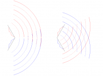
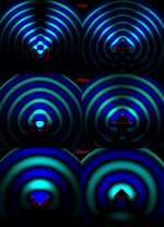
Few ripple tank sims, not too accurate since the UI is very coarse but should be in the ballpark. For anyone to test and wonder whats going on
Toe in ripple tank
Toe out ripple tank
Toe in ripple tank
Toe out ripple tank
Attachments
Last edited:
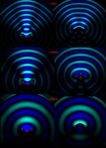
Here are 22 degree examples
toe out in ripple tank
toe in
Resolution should be ~50px corresponds to ~40cm, in which case the ripple tank setup should roughly match reality.
From the ripple tank tests it looks like the VituixCAD sims have the coordinates right. Toe in setup with 22 degree rotation has strong main lobe ~1kHz and weak side lobes. The toe out has narrow main lobe and wide side lobes, all almost equal in SPL.
From the ripple tank tests it looks like both have relatively few issues around where the crossover would be closer to 500Hz than 1000Hz. Although, the response may differ here significantly since both drivers interact with the physical construct which does not happen in VCAD sims I posted. I have no idea which one would work better in which situation. I strongly suggest build and measure since these are very quick and rough sims to give some idea how a system like this could work.
Attachments
Last edited:
Not so obvious, how about this...
I agree with tmuikku, this seems over simplified and incorrect for frequencies where the 15" radiators start to beam and form lobes, ie above ca 200hz.
^ if you checkout post #37 attachment the toe out setup seem to combine into nice wave front at least up to the ~700Hz test. The intensity seems to be quite uniform with wide dispersion. The toe in setup makes more distinct main lobe so narrower pattern overal. But jeah even the sims have lots of simplification baked in so 🙂 I think I've seen examples done both ways, from memory the toe in situation is quite rare though. Some high end products seem to have it (on the vertical axis). Most if not all big monitors using 15" side by side have them flat or toed out? In fact it is quite hard to google up images of these dual woofer systems, there is much more stacked vertically than in the horizontal configuration.
Here is someone building augsburger type thing, with toed in woofers. Some measurements of dual woofer setup in post #49, images and what not later in the thread.
Old School Studio Monitor Build | Page 3 | AVS Forum
Surely a system like this is cool looking but not sure if it is something one would want or need for sound quality. If they were good, they'd be everywhere instead of stacked drivers?🙂
Last edited:
- Home
- Loudspeakers
- Multi-Way
- Directivity of side by side woofers