Hi, I own a pair of Acoustat speakers that use direct drive amps. I'm looking to use/build supplementary electrostatic tweeters and drive them off the same amps -- which deliver ~4500v to the panels. I currently have some RTR tweeters (the blue ones akin to Arthur Janszen's design). I believe they require around 2000v so my understanding is that driving them off these amps would arc them to oblivion. That being said, I'm wondering if theirs a simple way to reduce the voltage being delivered to the tweeters while running them off the servo amps -- without incorporating a transformer in the signal path. Help would be greatly appreciated.
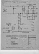
I have 10ea of the JansZen... type panels 130............here is the setup ....if you can see. the pic....stock bias....is 1100V neg....
I have used them with my Acoustat......with there own bias only...
But with some mods my Acoustat have all the topend I need...good luck
I have used them with my Acoustat......with there own bias only...
But with some mods my Acoustat have all the topend I need...good luck
Attachments
Why not make your own HV supply. I dd using one of these for each panel...
Electronic Goldmine - Battery Operated High Voltage Generator
I have a LM317 adjustable voltage regulator circuit varying the input (9vdc wall wart) to the HV supply from 1.25vdc to 8vdc giving me between 650vdc to 5000vdc....Works a treat on my experimental CLS panels.
Electronic Goldmine - Battery Operated High Voltage Generator
I have a LM317 adjustable voltage regulator circuit varying the input (9vdc wall wart) to the HV supply from 1.25vdc to 8vdc giving me between 650vdc to 5000vdc....Works a treat on my experimental CLS panels.
That almost seems too easy!
Have you had any issues with this design?
Have you had any issues with this design?
Why not make your own HV supply. I dd using one of these for each panel...
Electronic Goldmine - Battery Operated High Voltage Generator
I have a LM317 adjustable voltage regulator circuit varying the input (9vdc wall wart) to the HV supply from 1.25vdc to 8vdc giving me between 650vdc to 5000vdc....Works a treat on my experimental CLS panels.
I was wondering if you can wire those "Goldmine" units with the inputs in parallel and the outputs in series, using 4 of them to produce 8kV.
But my best guess is that the third one (covering 4001-6000v output) would not have the internal insulation to isolate the input wires from the HV output since it is designed to go only to 2000v.
I have a few EMCO power supplies, similar in character to the Goldmine but industrial quality. I suppose the same constraint applies to wiring them in series too?
Ben
Ben
Huh...I somehow got unsubscribed to this thread...
I have had no issues, but I do not need more than 2000v.
I don't see why you can connect them in series, you may want to check the input and output grounds - they should not be common....
That almost seems too easy!
Have you had any issues with this design?
I have had no issues, but I do not need more than 2000v.
I was wondering if you can wire those "Goldmine" units with the inputs in parallel and the outputs in series, using 4 of them to produce 8kV.
I don't see why you can connect them in series, you may want to check the input and output grounds - they should not be common....
I don't see why you can connect them in series, you may want to check the input and output grounds - they should not be common....
Sorry, I unable to understand what you are saying. Could you rewrite that and explain your meaning more clearly, albeit in more words.
Ben
I was wondering if you can wire those "Goldmine" units with the inputs in parallel and the outputs in series, using 4 of them to produce 8kV.
I haven't inspected this particular unit in person, but many other similar units I have seen share a common ground between input and output. If this is the case, your idea(inputs in parallel, outputs in series) will not work...maybe even generate some smoke.
It would be easy to remove the 0.015µF 2kV output capacitor and add 3 more multiplier sections to the one already on the board to get the desired 8kV.
Last edited:
I haven't inspected this particular unit in person, but many other similar units I have seen share a common ground between input and output. If this is the case, your idea(inputs in parallel, outputs in series) will not work...maybe even generate some smoke.
It would be easy to remove the 0.015µF 2kV output capacitor and add 3 more multiplier sections to the one already on the board to get the desired 8kV.
All true. And seems to be what john65b meant.
Minor fact, the EMCO series I have are wired with the input-negative to the case and all the outputs floating. So they could have parallel inputs and series outputs. But there would be voltages flying about that are higher than the ratings of the units when used conventionally (not in series).
I suppose it would be good practice when wired the conventional way to case-ground one terminal of the HV output (thus connecting it to input-negative). Thereby you'd have a ground network in the device box (for electrical as well as mental-map purposes). A separate (and disputable) question whether that ground network should connect to the mains ground.
Ben
Last edited:
All true. And seems to be what john65b meant.
Sorry, I keep getting unsubscribed to these threads...
I think if you toss the last 2kv cap, and introduce higher input voltage over 3vdc, you will get higher output. I think I put in 6vdc and got around 4-5kv out. I do not know what the voltage limit is on the remaining internal components...it would be pretty fun and easy to find out!
- Status
- Not open for further replies.
- Home
- Loudspeakers
- Planars & Exotics
- Direct driving ESL tweeter