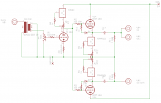
Here is a schematic for a linestage I want to make. I made a 76 tube resistance coupled amplifier with a voltage gain of about 9, and a 5687 tube buffer. I loved them both. Now I want to put the two together into a single unit. I didn't use any solid state in either but I want to in this one. I would use both halves of the 5687 for one channel, one for the regular out and one for a Sub out. I would set the 76 tube to 2.5ma and the 5687 tube to 20ma. The input transformer would be to correct the phase.
Please check out my work. I'm not sure about the direct coupling.
Athos
Please check out my work. I'm not sure about the direct coupling.
Athos
Attachments

One more try!
I understand there is a ton of these questions, but I'll ask one more time. Input welcome.
Athos
I understand there is a ton of these questions, but I'll ask one more time. Input welcome.
Athos
I didn't calculate voltages, so won't comment on operating points, but the basic design looks fine. I'd add a safety diode from grid to cathode on your followers.
Sheldon
Sheldon
I didn't calculate voltages, so won't comment on operating points, but the basic design looks fine. I'd add a safety diode from grid to cathode on your followers.
Sheldon
Thanks for the look, I go back and forth on those, I think though, since the part is cheap I might as well 🙂.
Athos
Attachments
Last edited:
I see no reason for the dc coupled version to not work. For what reason did they say it wouldn't?
I see no reason for the dc coupled version to not work. For what reason did they say it wouldn't?
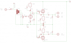
Hmm, not much of one really, I think there was a language barrier. However, I'm still nailing down the final schematic so I thought I'd show one with the coupling cap and gridleak. I really would like to couple it directly. I got my chassis and parts coming from Mouser and AES.
Athos
Nice idea. If i were to use a transformer i would expect it to do more that just invert phase. And the dc coupling is certainly doable, don't let language barriers spoil your sound 🙂 Btw, no need for a diode in the cap coupled version.
Another vote for the DC version, I'm glad to hear that my original idea was sound! I have a bunch of builds under my belt, but I get nervous when I cook stuff up myself 🙂.
Working
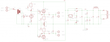
Well here is where it stands at currently. The front end is a simple 56/76 gain stage. The back end is a 5687 Aikido Cathode Follower copied from Mr. B at Tubecad.com. A couple questions, is anything amiss? Sounds different, not that it sounds bad, I think I need to tweak the cathode resistor of the 56/76 tube down a bit. I have the current for the 56s set at 4ma. I omitted two 1 meg resistors that Broskie has between the top 5687's grid and B+ and Ground, I don't believe their strictly necessary. Thanks
Athos
Attachments
Well here is where it stands at currently. The front end is a simple 56/76 gain stage. The back end is a 5687 Aikido Cathode Follower copied from Mr. B at Tubecad.com. A couple questions, is anything amiss? Sounds different, not that it sounds bad, I think I need to tweak the cathode resistor of the 56/76 tube down a bit. I have the current for the 56s set at 4ma. I omitted two 1 meg resistors that Broskie has between the top 5687's grid and B+ and Ground, I don't believe their strictly necessary. Thanks
Athos
Looks OK to me. The 1meg resistors are safety resistors, to prevent a large spike to the power amp, in the event of a fault in the input stage. If your system can take it, they are not strictly necessary. Just for fun, you might try the mu follower connection (take the output from the first stage between the FET chip and the anode resistor).
Sheldon
Thanks for the view. Two issues that cropped up during listening today. I need a mute switch (tonight's project) and I need to figure out the source of a bit of low frequency "noise." What happens is a few low level taps come out of the sub every once and a while, not very loud. I also need to re-integrate my filament supplies. Could the low frequencies be a bad cap? One of my filter caps got a nasty jolt above its rating for a few seconds.
Athos
One more important question, I lifted the filaments with a voltage divider off of B+ to the CT, is it ok to leave that connection and then rectify and regulate?
Athos
Athos
Thanks for the view. Two issues that cropped up during listening today. I need a mute switch (tonight's project) and I need to figure out the source of a bit of low frequency "noise." What happens is a few low level taps come out of the sub every once and a while, not very loud. I also need to re-integrate my filament supplies. Could the low frequencies be a bad cap? One of my filter caps got a nasty jolt above its rating for a few seconds.
Athos
It might be a bad cap, but I've yet to experience that problem. I have had similar symptoms with a bad solder joint, or poor tube pin connection. Is the filter cap an electro or film, and how much above the rating was the spike?
Sheldon
One more important question, I lifted the filaments with a voltage divider off of B+ to the CT, is it ok to leave that connection and then rectify and regulate?
Athos
Not sure I understand. Do you have a schema for this?
Sheldon
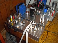
I installed a mute, and replaced the suspect electrolytic cap. It was rated for 500v but got around 600v  .... In the process I reheated a bunch of joints so hopefully the issue is resolved 🙂. For the heater lift look at post #10, the heater bias is connected to the CT of the filament winding to raise it to ~1/4th b+, I'm not sure how that works if the supply is rectified. Still sounds good. I think I need to take a break from this one and tinker with my 6V6pp amp some more...
Thanks for the assistance Sheldon.
Athos
.... In the process I reheated a bunch of joints so hopefully the issue is resolved 🙂. For the heater lift look at post #10, the heater bias is connected to the CT of the filament winding to raise it to ~1/4th b+, I'm not sure how that works if the supply is rectified. Still sounds good. I think I need to take a break from this one and tinker with my 6V6pp amp some more...Thanks for the assistance Sheldon.
Athos
Well it needs more trouble shooting, I spent a while listening at the speaker, the noise sounds like a record needle scratching, happens every once and a while.
Athos
Athos
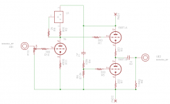
Is the output intended to be a white cathode follower?? Because as drawn it is not and in fact there should be a resistor between the plate circuit, ac voltage divider and the supply. Right now as drawn the lower tube is basically loading the upper tube, and not contributing any drive. (I did not look at the inspiring circuit.)
If it is intended to couple supply ripple in order to cancel it I'd say you might want to fix that problem at the source, and come up with a better CCS than that tube.
Note also that the 5687 is fairly prone to VHF oscillation if the grid stopper resistors are not installed right at the socket grid pins.
Last edited:
- Status
- Not open for further replies.
- Home
- Amplifiers
- Tubes / Valves
- Direct Coupled 76/5687 linestage