Hi all!
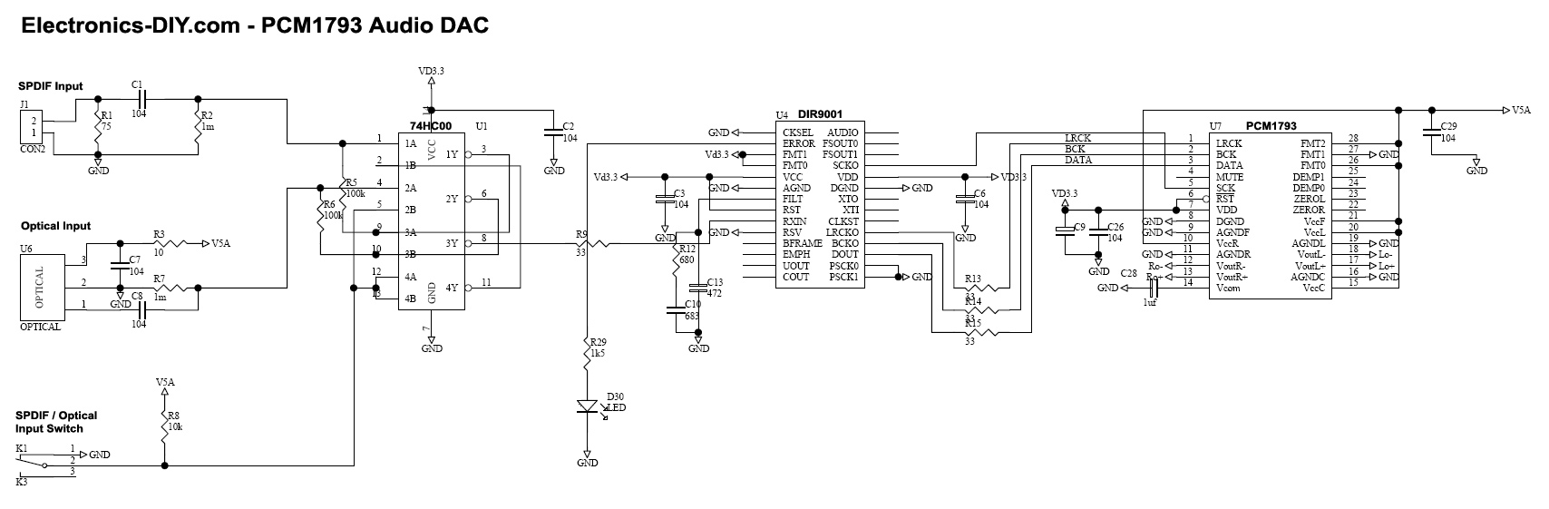
Im having problems with the attached circuit based on the DIR9001 96kHz s/pdif receiver from Texas. Problem is that xaudio=0 and error=1 all the time no matter what.
This is only kind of proof of concept and not nearly a final solution so there's no decoupling caps and I'm using the same vcc/vdd and dgnd/agnd respectively.
Can you see anything obviously wrong with the attached circuit?
Attachments
Thanks, that was fast. According to specs, CKSEL is pulled internally pulled low but I'll give it try.XTI should not be grounded, should be High (disconnected). Connect CKSEL to GND for PLL mode (or to ERROR for AUTO mode).
Sorry, that was a typo - my C1 is actually 4n7F.Disconnected GND from XTI and tied CKSEL to GND - no go. Tried CKSEL to ERROR but it still no go. Got any more ideas?
Again sorry, there were more typos with the other caps - here's my currently updated schematics. I'm a total noob at this and it's my first time ever using Eagle.
The reason for the two paralleled caps making for 69nF together and two resistors adding up to 692R in series is that I didn't have the proper values - are these close enough, you think?
Attached is also a picture of the soldering, looks ok?
The reason for the two paralleled caps making for 69nF together and two resistors adding up to 692R in series is that I didn't have the proper values - are these close enough, you think?
Attached is also a picture of the soldering, looks ok?
Attachments
Added some, didn't change anything.Decoupling caps are also recommended.

Thank you, the first schematic is new to me so I tried that without any luck though. The second is from the datasheet which I based my own schematic on.
Regretfully, it seems I'm facing bad soldering or a broken chip. I soldered @ approx 350 celcius and afterwards I noticed from specs that the chip can withstand a max of 260 for 5 seconds...
Thanks for all your help guys!
Regretfully, it seems I'm facing bad soldering or a broken chip. I soldered @ approx 350 celcius and afterwards I noticed from specs that the chip can withstand a max of 260 for 5 seconds...
Thanks for all your help guys!
Yep, temperature can kill your chip... Use a good low-temperature solder and use 365°F temperature - the chip won't get hot if you limit the exposure time and quantity of solder.
For desoldering I use this.
The 63/37 ratio, known as eutectic solder has practically no plastic range, and melts almost instantly at 183°C (361°F).
For desoldering I use this.
The 63/37 ratio, known as eutectic solder has practically no plastic range, and melts almost instantly at 183°C (361°F).
Last edited:
Sadly not so i put that project on hold in favor of others. The chip is fairly easy to work with so in retrospect, I think my soldering was bad, i.e. I overheated the chip while soldering.hi hanzibal,
did you fix the problem? does your DIR9001 work?
I'm a having quite the same problem... error = 1
I checked the signal at RXin with the oscilloscope and there was nothing wrong, yet there are no signals at LRCK, BCK, SCK...
I'll be taking the project up again as I will be needing an SP/DIF receiver for upcoming projects. Don't know exactly when this will happen though.
As for your problem, it could still be unsupported input format. AFAIK, the chip only accepts regular PCM audio @ 96kHz max. That is, not any of the many encoded/compressed or multi-channel formats (like DTS and similar).
If I remember correctly there's an error pin out that you could check.
Hope this helps.
Same problem here, feeding the chip a nice TTL signal and still the ERROR pin is high.
Wired according to this: 24-Bit 192KHz PCM1793 DAC with DIR9001 Receiver and OPA2134 OPAMP
Wired according to this: 24-Bit 192KHz PCM1793 DAC with DIR9001 Receiver and OPA2134 OPAMP
Seems this problem is back after I soldered the coax-TTL circuit on veroboard. Might have less capacitance now compared to breadboard though, anybody knows how sensitive it is? Still on the scope the input signal looks good.
On the FILT pin, the voltage is pretty constant 0.8V, has anybody measured that?
RESET is done from PG output of 3.3V supply, that should be OK? Datasheet says it should be lifted within 100ns of stable supply. Seems most just wire it to supply.
On the FILT pin, the voltage is pretty constant 0.8V, has anybody measured that?
RESET is done from PG output of 3.3V supply, that should be OK? Datasheet says it should be lifted within 100ns of stable supply. Seems most just wire it to supply.
- Status
- This old topic is closed. If you want to reopen this topic, contact a moderator using the "Report Post" button.
- Home
- Source & Line
- Digital Line Level
- dir9001 problems