To give you a better example, check out this link and take a loot at the frequency responses of 1628-SE and JS-6123.
Un title page
Instead of the common Ls/Cp underdamped peaking, it is visible as a dip. During my experience with making my own transformers, I've had this dip occurring in some project as well and I came to the conclusion it's still related to Ls and Cp, but probably interconnected between the layers in a different way (probably parallel) to occur as a dip.
I'm yet trying to find the reason, what winding, interleaving or interconnecting characteristics makes this resonance appear as a dip?
One suspicion it is, it could be somehow related to a primary interlayer Cp resonating with Ls. A connection between primary layers for lower primary clumped capacitance shifts the resonant frequency and decreases amplitude.
Decreasing the driving impedance increases the amplitude of the dip. Another logical explanation of it could be a parallel resonance between primary inductance and clumped capacitance. It makes sense that, at high frequency, core losses will be high, hence a low Lp and a high Q parallel tank.
Although I don't buy it at 100%, because this same nature of resonance occurred with low loss amorphous cores and changing Lp by moving the air gap did not shift this resonance.
Last edited:
Hi,
I've found that primary sections may have they own resonant frequency according to they own inductance and lumped capacitance. The lumped capacitance is negligible when the winding use a single layer but becomes very hight with two layers and, of course increase with the size of the transformer. Insulation between layers helps in reducing the capacitance. The situation is better with more layers because these capacitances are then "in serie".
As a joke, if you target low frequency performance use more iron, if you target extended hi frequency response use more paper")
Yves
I've found that primary sections may have they own resonant frequency according to they own inductance and lumped capacitance. The lumped capacitance is negligible when the winding use a single layer but becomes very hight with two layers and, of course increase with the size of the transformer. Insulation between layers helps in reducing the capacitance. The situation is better with more layers because these capacitances are then "in serie".
As a joke, if you target low frequency performance use more iron, if you target extended hi frequency response use more paper
Yves
I found it again - the resonance doesn't occur when all secondary sections are in parallel.
But when some of them are in series, this resonance occurs.
This joke is quite a fact! I'm also using more "air" for better HF
But when some of them are in series, this resonance occurs.
As a joke, if you target low frequency performance use more iron, if you target extended hi frequency response use more paper
This joke is quite a fact! I'm also using more "air" for better HF
Last edited:
it is a lot of PITA
You can also do a williamson type output transformer but with 4 sectors instead of only 2. You will have very good low end and high end also because the coils are wound symmetrically.
Welcome to the most complete do it yourself guide on the D. T. N. Williamson tube amplifier.
You can also do a williamson type output transformer but with 4 sectors instead of only 2. You will have very good low end and high end also because the coils are wound symmetrically.
Welcome to the most complete do it yourself guide on the D. T. N. Williamson tube amplifier.
I need to think about it using a clear head, which is not possible atm... too immersed with my problem.
Your stuff seems to be a hybrid between PI winding and interleaving, right?
P.S. I'm having extremely good success by distrubing the capacitance more across the primary to primary layers than to the secondary layers. Now the resonance is almost gone and reaching 200kHz.
Your stuff seems to be a hybrid between PI winding and interleaving, right?
P.S. I'm having extremely good success by distrubing the capacitance more across the primary to primary layers than to the secondary layers. Now the resonance is almost gone and reaching 200kHz.
Well it's not my stuff... I base it on old ham radio books and my experience with high efficiency and high frequency switch mode power supplies.
Best transformers I used were wound like that... You get good coupling from primary to secondary. Best method for insulation transformers (when primary and secondary are identical) is to twist the wires and then wind with them.
My proposal is similar it's an interleaving of the primary and secondary and should have better frequency response and lower copper losses.
Silviu
Best method for insulation transformers (when primary and secondary are identical) is to twist the wires and then wind with them.
You mean mains isolation transformers? Well, that's not a good idea at all! Proper mains isolation transformers are wound on split bobbins, one chamber for the primary, the other one for the secondary winding.
Best regards!
Here's a really good paper on transformer modeling --Transformer Modelling
while the examples show use of Omicron's Bode 100 you can perform all the analysis with a signal generator and o'scope, or your own VNA
while the examples show use of Omicron's Bode 100 you can perform all the analysis with a signal generator and o'scope, or your own VNA
Last edited:
jackinnj,
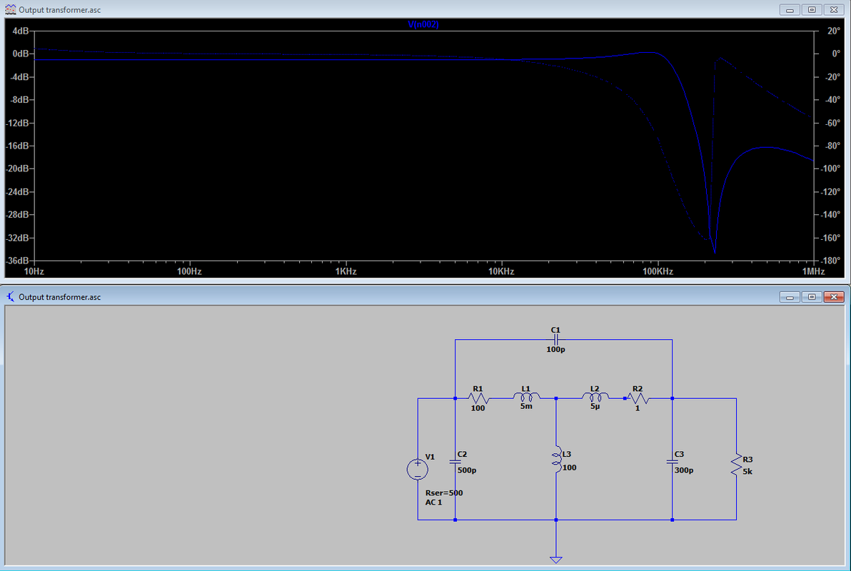
Thanks! The document you posted actually leaded me to even more valuable literature. I found "Wideband transformer models" by Chris Trask. The model model he published on his work makes a lot of sense actually.

The dipping capacitance can be seen as a result from a high C12 interwinding capacitance mixed with leakage primary and secondary
inductances.
Here is a SPICE sim with practical values.
Thanks! The document you posted actually leaded me to even more valuable literature. I found "Wideband transformer models" by Chris Trask. The model model he published on his work makes a lot of sense actually.
The dipping capacitance can be seen as a result from a high C12 interwinding capacitance mixed with leakage primary and secondary
inductances.
Here is a SPICE sim with practical values.
Last edited:
- Status
- This old topic is closed. If you want to reopen this topic, contact a moderator using the "Report Post" button.
- Home
- Amplifiers
- Tubes / Valves
- Dipping resonance of some audio transformers.