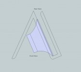
I was playing around in Google sketch-up trying to come up with a lower profile version of a traditional H-Frame or even open baffle woofer. This sketch is a top view for a woofer designed to roll-off between 200-300Hz and augment a full range driver.
The woofer would be wired with reverse polarity in relation to a full range driver. The front of the driver fires into a chamber which exits at the rear of the design to help isolate the rear wave. The design may also benefit from a slight horn-loaded shape facing front. Note that the top of the chamber would be solid to minimize wave interaction.
Im interested in your initial thoughts with regard to possible advantages/disadvantages over a standard open baffle design. Also, any guesses as to how SPL would be affected in comparison to an open baffle, H-frame, etc.
Thanks as always!
Attachments
To me it looks like a cross between Z Frame and a Ripol.
The narrow path facing the cone will introduce some mass
reactance, since it sems less than the cone's area in cross section ?
I do not state this being good or bad, but the free air resonance of
the driver will lower somewhat and the Q will rise.
This may be desirable for many drivers. The dipole path length seems
a bit short, making it longer would decrease the displaced volume
needed for a certain SPL goal.
Horn like shape is very much less important than
dipole path length. A flared "port" may reduce noise,
but there will be no serious effect in SPL i feel.
I guess you have consulted Linkwitz' spreadsheet to
estimate max SPL due to dipole path length and
displacement volume for your driver ?
Kind Regards
Oliver
Hi Oliver, good to hear from you again.
Yes. I am hoping in increase total Q by firing the driver into a narrow path less than the cone's cross section. Think of an automotive woofer being fired into a small chamber in a band-pass configuration. Since the woofer is only working at the lowest few octaves, and overlaping the full range driver, im not too concerned about a steeper roll off. I think my design would benefit from a higher Qts as well.
With regard to measuring the dipole path at the front of the enclosure (rear of the driver), this is a bit challanging due to the irregular relation of the driver to the side walls. I suppose I could go for an average measurement, an imaginary line drawn from the center of the magnet out until it's parallel to the end of each wall?
It might be easier for me to build the "carrier" this weekend, and play with the length of the side walls, and depth of the chamber, and measure the result.
Ed
The narrow path facing the cone will introduce some mass
reactance, since it sems less than the cone's area in cross section ?
Oliver
Yes. I am hoping in increase total Q by firing the driver into a narrow path less than the cone's cross section. Think of an automotive woofer being fired into a small chamber in a band-pass configuration. Since the woofer is only working at the lowest few octaves, and overlaping the full range driver, im not too concerned about a steeper roll off. I think my design would benefit from a higher Qts as well.
With regard to measuring the dipole path at the front of the enclosure (rear of the driver), this is a bit challanging due to the irregular relation of the driver to the side walls. I suppose I could go for an average measurement, an imaginary line drawn from the center of the magnet out until it's parallel to the end of each wall?
It might be easier for me to build the "carrier" this weekend, and play with the length of the side walls, and depth of the chamber, and measure the result.
Ed
- Status
- Not open for further replies.