I made a test baffle for a dipole experiment, its using a 5" driver
After making on-axis frequency response measurements I saw a deep -11 dB dip at around 1500 hz
Then I remembered I've seen something that might help on some thread and I saw this post made by Planet10
http://www.diyaudio.com/forums/showthread.php?postid=110699#post110699
Now I am interested in why does that happen? I've tried finding more info on this subject whitout success.
Does that happen only when the baffle is square? Mine is rectangular. Does it depend on surface materials?
Any ways to predict that? Math models?
I'll make a new test baffle to compare and see..
And one more thing
sfdoddsy, In here
( http://www.diyaudio.com/forums/showthread.php?postid=110771#post110771 )
you are talking about some nitrite rubber you have used on your dipoles, I visited your website and it sure looks awsome, did you see any concrete sonic differences? and where did you find that rubber?
Thanks in advance for any help you guys can provide.
The strangest part is that when I simulate a bandpass (500hz/2000hz) filter on that freq response, the dip dissapears completly.
:\
:\
You might try out the BDS software that the FRD Consortium has (free) on their website. It does a really good job of modeling baffle effects for different geometries and driver placement. I haven't tried it for dipoles yet, but no reason it shouldn't work.
There is some discussion of diffraction effects with open baffles here:
I belive this is wht Linkwitz recommend crossing over the midrange at about 1400Hz, to prevent this.
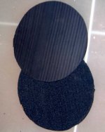
The rubber on my speakers is 6mm foam backed nitrile. I got it from a local rubber store in Australia. I would imagine that a good hardware or rubber store should be able to source it.
Here's a shot of either side:
I belive this is wht Linkwitz recommend crossing over the midrange at about 1400Hz, to prevent this.
The rubber on my speakers is 6mm foam backed nitrile. I got it from a local rubber store in Australia. I would imagine that a good hardware or rubber store should be able to source it.
Here's a shot of either side:
Attachments
Hi Ilianh,
Maybe the spreadsheet attached to the linked page can be of interest. Look for "Le baffle-plan" and in the middle of the page "Feuille de calcul"
http://members.aol.com/petoindominique/choix/nb_voies_s.htm
Allows you to calculate freq response based on dimension, placement of the speaker in the baffle, placement above the floor and Qts. It also shows the change in response with a series resistor added.
I recommend you to change the scale of the frequency axis to logarithmic.
By the way, it's in Frech. If you don't speak French or want a good laught use any automatic translator.
I have not done a reality check of the accuracy yet. Still running in my cheap Monacor SP-200-X.
Incidentally, this is my first post on this forum, so Hello everybody.
Miguel
As far as the sound of rubberizing the baffle, it's hard to say. I changed drivers at the same time as I stuck on the rubber and the speakers do sound better, but that's to be expected.
Steve
Steve
One more thing: there's nothing magic about nitrile rubber. Whichever material you pick, make sure that it's an open cell foam. Foams with some sort of heavyish filler will generally have the highest absorption. McMaster-Carr is a treasure trove of materials.
Or you could be a natural sort of guy and use thick felt.
sfdoddsy's suggestion is an excellent one- anyone building dipoles ought to give Linkwitz's site a good read.
Or you could be a natural sort of guy and use thick felt.
sfdoddsy's suggestion is an excellent one- anyone building dipoles ought to give Linkwitz's site a good read.
Thanks to all for those helpful replies.
I already read this paper on dipoles by Mr. Linkwitz.
Thats how I started my dipole project, but he is doing it using active crossovers, and active notch filters. I am doing it all passive. :|
this could be corected easily if i was oding it active.
I just finished reading this:
http://members.aol.com/petoindominique/choix/nb_voies_s.htm
(hehe, I'm just lucky I speak french)
and what I'll try when I get back home, is to make another test baffle, and to put the driver slightly off center, even if the baffle is already rectangular with folded sides.
I didnt try the BDS software yet, I'll do it when I get back home.
I'll post some graphs too.
Ilianh,
Quickly skimmed over the thread, and the other one you linked to. Just want to make sure that diffraction and dipole cancellation aren't getting confused here.
When you are looking at dipole cancellation, you should see a dip, followed by a large peak, and then dipole rolloff.
baffle d= half wavelength= first dip (sometimes very small because the driver basket acts like a low pass filter on the rear radiation...)
baffle d= one wavelength= subsequent peak because front and rear radiation now sum(almost always larger than dip), then dipole rolloff. Olson's diffraction graph is not representative of dipole cancellation.
I think you are looking at simple diffraction.
I don't like to offset drivers because I prioritize off axis FR over diffraction.
This dip will be affected by baffle width and crossover point.
One thing I like to do to is router the front edges with a large radius roundover bit to smooth diffraction effects.
regards, Jason
- Status
- Not open for further replies.
- Home
- Loudspeakers
- Multi-Way
- Dipole issues