"Mid off axis - straight connection (No xo)" Strange result if direct coupled. Same on both? Compair Distortion tabs between L & R, to see if one have had a coil melt.
Both looks the same L and R.
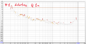
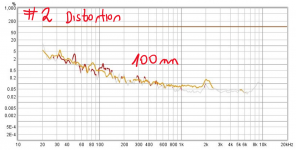
Distortion measurement looks good. I will upload it.
add near field measurements
Added two measurements sessions.
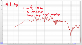
Number 1 are from 1m with gated window of 20ms 20deg off axis.
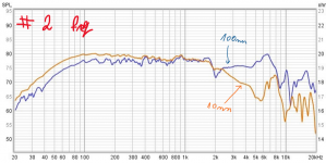
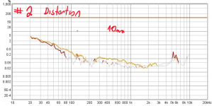
Number 2 are near field: 10mm and 100mm 0 deg off axis
Added two measurements sessions.
Number 1 are from 1m with gated window of 20ms 20deg off axis.
Number 2 are near field: 10mm and 100mm 0 deg off axis
Attachments
Looks good Iron SF. One can se the characteristics from the pdf.
https://www.morelhifi.com/wp-content/uploads/2019/12/TSCM634.pdf
Maybe this midrange is very picky on angles or else it running the staircase.
https://www.morelhifi.com/wp-content/uploads/2019/12/TSCM634.pdf
Maybe this midrange is very picky on angles or else it running the staircase.
Measuring vertical angles with both drivers would show more about the crossover.off axis
No, better closer than that. You don't need to get very low frequencies, not near the crossover, so you can gate. This way you only see the varying effect of the cross and don't look at the room.
You can do this other ways, I've simply noticed that you are using measurements so this way will give you the answer you need.
You can do this other ways, I've simply noticed that you are using measurements so this way will give you the answer you need.
Well, the nearfield measurement compared with the measurement on 1m still don’t rule out a weird kind of baffle step function, combined with a too fast decay above 2k of this specific unit.
I’d measure the driver on a big baffle, preferably IEC dimensions, so one should read data sheet values. If that’s the case, design another baffle of your speaker, as virtually every critical distance is in the range of the wavelength associated with 2k. But I suspect the driver not to be fully OK.
I’d measure the driver on a big baffle, preferably IEC dimensions, so one should read data sheet values. If that’s the case, design another baffle of your speaker, as virtually every critical distance is in the range of the wavelength associated with 2k. But I suspect the driver not to be fully OK.
Measuring vertical angles with both drivers would show more about the crossover.
As long as the mid alone has this almost step function at 2k, trying to design a crossover is pointless. Just my 2ct.
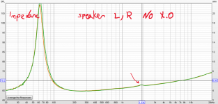
Btw Just noticed the data sheet shows a little bump in the impedance curve. Where? At 2k! Did you measure your impedance curves?
Last edited:
As long as the mid alone has this almost step function at 2k, trying to design a crossover is pointless. Just my 2ct.
Btw Just noticed the data sheet shows a little bump in the impedance curve. Where? At 2k! Did you measure your impedance curves?
Attached are the impedance measurements:
Attachments

Last edited:
Well, the nearfield measurement compared with the measurement on 1m still don’t rule out a weird kind of baffle step function, combined with a too fast decay above 2k of this specific unit.
I’d measure the driver on a big baffle, preferably IEC dimensions, so one should read data sheet values. If that’s the case, design another baffle of your speaker, as virtually every critical distance is in the range of the wavelength associated with 2k. But I suspect the driver not to be fully OK.
Thanks
What are the IEC dimensions?
Ran
IEC should be 1m x 1m. I'd try that driver on anything you have handy that isn't the same size of your finished baffle, just to get a handle on what this is. The impedance wrinkle seems too small to have that big of a result in frequency response. Almost seems like the driver has a mechanical issue like non-linear suspension compliance.
Last edited:
It is interesting to look at the breakup modes of this woofer. It is not completely clear which of these is setting the reasonable upper limit to the usability of the driver, are we assuming at this point that it can be used up until general directivity runs aground?As long as the mid alone has this almost step function at 2k, trying to design a crossover is pointless. Just my 2ct.
That assumption suggests that cone resonances are to be equalised.
In addition, it may be cone breakup that is causing the impedance blips, do you think?
It could be cone breakup (the 2k dip). But once that occurs, irregularities in the response rule. This measurement shows a dip, followed by a rather clean response higher up the frequency range. Strange indeed. The fact that the dip persists off-axis would indicate it is not diffraction-induced cancelling.
@ OP, how is the mid enclosure constructed? Which internal dimensions, what damping (acoustic stuffing) is applied? Are you able to produce CSD or BD plots? Were the impedance measurements done in free air or in the enclosure?
@ OP, how is the mid enclosure constructed? Which internal dimensions, what damping (acoustic stuffing) is applied? Are you able to produce CSD or BD plots? Were the impedance measurements done in free air or in the enclosure?
I'm as yet uncertain that breakup can be summarily dismissed based on the current information, but willing to be shown otherwise.
If the extant problem is only response irregularities, then can't we equalise it?irregularities in the response rule.
Ran, try put the naked driver on the bench and run a measurement, if the dip still exists then it's most probably related to the driver itself and other variables can be ruled out.
Well, I don't rule it out either. But this graph keeps me puzzled. Why would a grille (cloth on a wooden frame) be maleficial to a cone breakup? Waiting for the CSD/BD-plots!I'm as yet uncertain that breakup can be summarily dismissed based on the current information, but willing to be shown otherwise.
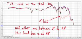
If you giving a tilted box a tilt, you get no tilt! Keep us confused 😀
🙂 the tilt test was done on the test box which add no built in tilt
Thanks
If you giving a tilted box a tilt, you get no tilt! Keep us confused 😀
IEC should be 1m x 1m. I'd try that driver on anything you have handy that isn't the same size of your finished baffle, just to get a handle on what this is. The impedance wrinkle seems too small to have that big of a result in frequency response. Almost seems like the driver has a mechanical issue like non-linear suspension compliance.
I will do this test and update. but it will take me a while.
Thanks
- Home
- Loudspeakers
- Multi-Way
- Dip in the mid