Hi there guys,
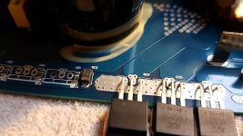
Does anyone know the exact part number of the Diode 15B-34 from the photo? When I search this I get all different kinds of diodes.
It is used on the output section of a Soundmagus 3500x (same as the excursion HXA5k)
diode number D34, D35, D37, D38
Thanks 🙂
Does anyone know the exact part number of the Diode 15B-34 from the photo? When I search this I get all different kinds of diodes.
It is used on the output section of a Soundmagus 3500x (same as the excursion HXA5k)
diode number D34, D35, D37, D38
Thanks 🙂
Attachments
Only one side of the the amplifier (2 of the 4 output banks) read different values on the diodes. The faulthy 2 banks also have no PWM going to the gate of the fet (IRF640N).
One of the diodes is shorted, the other reads 0.60v
One of the diodes is shorted, the other reads 0.60v
. One of the diodes is shorted, the other reads 0.60v
Check the associated capacitor also
15V zener: http://www.taitroncomponents.com/catalog/PDF/TOC/SMD 2-Terminal SMB Zener-3W.pdf with marking 15B.
I repaired a lot of these amps but these diodes never failed.
I repaired a lot of these amps but these diodes never failed.
A 15v Zener makes sense but I've seen a 1N4148 in that location. I didn't get a reply from the OP but was going to suggest that voltage (above the suspected Zener voltage) be applied through a resistor (1k?) to see if the breakdown voltage could be identified.
This method of checking breakdown voltage was regularly useful for diodes/Zeners and other components. I had a variac that I drove into a bridge rectifier and capacitor to get to about 200v DC for testing. Maybe someone else will find this useful.
This method of checking breakdown voltage was regularly useful for diodes/Zeners and other components. I had a variac that I drove into a bridge rectifier and capacitor to get to about 200v DC for testing. Maybe someone else will find this useful.
Thank you very much for all replies Perry, Bertje, Rayma.
Perry, Yes I have a 30v regulated power supply.
0-30v
0-10a
A very helpful tip about how to find the breakdown voltage. Thank you very much.
Thanks Bert 🙂
A very helpful PDF file.
Some 15v zeners are ordered.
Do you have experience with the output section of these amps Bertje? This is the first time I have one of these amps, with this layout.
I measured and saw this amplifier uses only one PWM module board which is powering the 2 (Optocoupler 6n137 driver board???) on each side of the output section.
From that (Optocoupler driver board) the PWM is directly going to the output fets.
One side of the amp (2 out of the 4 banks) has a little wobble in the Hi and Low peaks of the PWM going to the gates.
I measured the PWM INPUT pin from that optocoupler boards and there is a nice clean PWM signal going in. Also another pin has the transformed power supply PWM on it, which comes out wobbly out of the transformer. I suspect this has something to do with the problem. That transformer is driven properly by the power supply fets.
Have you had this problem before with these amps?
The other bank had blown zener diodes and creates no PWM out of the Optocoupler board, while the INPUT pin of that optocoupler board has a nice clean PWM on it as well.
I suspect this is caused by the leaking zeners. Hope to have them in house quickly ^_^
The design is really old, like from Sinus Live SL-A1500. A lot of brands use this design in different variations of amps (eXcursion, Xfire, Amp, etc)
There are diagrams available, just search on this forum. The opto's and some parts on both driverboards are often defective, I always change 16x IRF640N at the same time, same batch. Check the gate resistors also(10 ohm). The PWM board never failed actually...The factory use a lot of thermal grease (far to much imho...) and solderings are really bad. But they are cheap and deliver a lot of powerrr.
There are diagrams available, just search on this forum. The opto's and some parts on both driverboards are often defective, I always change 16x IRF640N at the same time, same batch. Check the gate resistors also(10 ohm). The PWM board never failed actually...The factory use a lot of thermal grease (far to much imho...) and solderings are really bad. But they are cheap and deliver a lot of powerrr.
Last edited:
- Home
- General Interest
- Car Audio
- Diode 15B