Hi,
do anyone know of a diy-design (schematics/code) for
a vu-meter fed by a spdif/I2C audio-signal? (just for reference)
The swedish version of Elektor had such a project in 1996
using a cs8412 and an ADSP2105 with custom written software
which one had to buy.
It would be fun to design it myself using a fast pic or maybe a dsp, using the
signals from an spdif receiver chip like cs8412 or similar.
but as it involves
mathematics on audio signals to compute average/peak
detection, I need some source of information on how to
do those calulations.Im not looking for a very accurate
display.I want to use the upper and lower vertical segments of 6 7-segment displays to show average or peak-detection of a 16 bit stereo-signal.
In other words, 12 bars for each channel.that would be
5dB for each bar for a standard 60db vu-meter .
Basically, I need some feedback or links with info to get me
started.
thanks in advance for any advice!
By far, the easiest thing to do is use a DAC and a LM3914.
I've done VU/PPM metering, in an embedded application using an Analog Devices SHARC DSP.
Using a regular PIC is out of the question; you need something with I2S capability, unless you want to put a CPLD or something on the I2S stream in order to transform I2S into something more microcontroller-friendly. So you're stuck with a DSP of some sort, or maybe a dsPIC.
For the math involved, the LM3914 datasheet and appnotes have all sorts of good information on VU and PPM metering, and the math functions involved. PPM (attack/decay) metering is easy using straight multiplies/adds/compares, and VU is a 5th (?) order IIR filter.
before I did the opening post I did actually consider using
a simple cs 4334 dac, 2 x 2 cascaded lm3915 accompanied
with ops and passives to do the rectification.but I would also
need large pic to convert the 2 x 12 taps of the lm3915s and
convert to single bytes to be transferred serially to the pic that actually controls the led segments.I want VU operation on the
segments when that pic is doing nothing else, and the displays
would normally be dark.
so all in all, a very high component count for the VU function,
and not very elegant.I remember using a lot of logic circuits
in the past to avoid using pics/splds, but found out that in the
end, learing to use new parts is not a bad thing, and in those
cases, not very difficult either.
I have never touched a dsp before, and until now I did not
know exactly what an iir filter is/does, but I have done some
digging into the subject and I think this particular
project could be a nice way to learn something about it.
As I see it, I need to find out which dsp could be suitable for
the task, and I need to learn about digital filters
to be able to implement vu-function in it.I suspect it will not be a very easy task.
Digital PPM/VU meter
Hi Yulquen
I implemented a 'digital PPM 'in an FPGA for an all-digital amplifier application. It has an instantaneous peak attack with a 'hold hat', ie the most recent peak LED holds on for about a second. This design is not a True-PPM in sense of the ballistics, but it has has practically sensible dynamics. There are 21 LEDS: a red for 0dBFS, 10 yellow for 1dBFS to -10dBFS in 1dB steps, and 10 green in a logarithmic progression down to about -60dB. An earlier design I did had LEDs down to -96dBFS but in practice this is pointless. The design is a VHDL module designed to accept mono input in parallel form. In a stereo design with i2s input, two such modules and a deserialiser would be needed. My implementation is fairly intensive of logic cells, but FPGAs of sufficient size are cheap nowadays .
If you want exact True PPM dynamics as traditionally used in the broadcast industry, you could precede the meter modules with an IIR filter. Personally I wouldn't bother. It's notable that the workhorse instrument of the industry, the Tek 746 digital audio meter, doesn't have 'classic' PPM dynamics for its 4 level meters.
Regards
John Hope
Hi John,
Sounds nice the implementation in an FPGA.
Is it available for diy from you.
Can you give info about the FPGA you use. Is it from Xilinx.
Gene.
Sounds nice the implementation in an FPGA.
Is it available for diy from you.
Can you give info about the FPGA you use. Is it from Xilinx.
Gene.
The Texas Instruments TAS3103 DSP contains VU metering capabilities. This easy to use DSP needs absolutely no programming whatsover - it is a audio-specific DSP which provides a set of pre-programmed functionality which is accessible by configuring the appropriate parameters (e.g. filter coefficients).
The TAS3103 has 10 channels of VU metering. It can be configured in many ways, like 2 channel full-range VU meter, 2 channel 5-band spectrum analyser, or mono 10-channel spectrum analyser. The RMS-estimators are fully configurable for attach/decay etc.
This DSP also incorporates many other powerful audio features including about 20 bands of EQ and/or filters (bi-quad filters), dynamic range compression/expansion (good for restoring old compressed recordings), tone control with configurable filters, a "3D" channel-mixing matrix, and others. And nothing requires any code to be written.
Member
Joined 2002
thanks for your suggestion macboy, I will give this a go,
I have now ordered some samples of this chip.
I have now ordered some samples of this chip.
digital VU/PPMs
Hi gene_klein and others
Attached are the VHDL files for the all-digital PPMs I use in my PowerDAC amplifiers. I used a Xilinx XC2S50 FPGA, which had a whole lot of other unrelated logic in it as well. A few explanatory notes are in order about the VHDL modules in the attached zip file:
The main file is vu_ppm.vhd - a mono PPM module - which accepts parallel rectified audio vector of 16-bit width, called LR_RECTWORDS. The output for driving the LEDs is 21-bit activ-hi vector BARLED.
The various clock signals are obtained from a module in another file, sysgen.vhd.
i2s_iface.vhd implements an i2s receiver and generates the rectified audio vector to the vu_ppm.
Note that the 64fs bitclock supplied externally - the i2s bitclock -serves as a global clock to everything, and that the system is inherently L/R time division multiplexed so that a given channel's vu_ppm is updated only for that channel.
In my implementation I sampled the LEDBAR outputs of the 2 vu_ppms and serialised them using the module slizer.vhd. This serial 'LED bus' was taken out of the FPGA to feed to remote LED driver-shift-registers, but this is not strictly necessary, unless like me you prefer serial to parallel interconnects.
It's difficult to properly explain this lot at system level without the top level heirarchy diagram, but this is only readable on the Xilinx IDE. If anyone has the facility to read it, and wants to, I can archive the entire FPGA project and post it.
If all this looks horribly over-complicated you can make a dead simple digital PPM by simply driving each LED in an array of n LEDs from the nth bit in a parallel audio word. It's pretty but sadly pretty useless for practical metering.
Hope this is of use
Cheers
John Hope
Hi gene_klein and others
Attached are the VHDL files for the all-digital PPMs I use in my PowerDAC amplifiers. I used a Xilinx XC2S50 FPGA, which had a whole lot of other unrelated logic in it as well. A few explanatory notes are in order about the VHDL modules in the attached zip file:
The main file is vu_ppm.vhd - a mono PPM module - which accepts parallel rectified audio vector of 16-bit width, called LR_RECTWORDS. The output for driving the LEDs is 21-bit activ-hi vector BARLED.
The various clock signals are obtained from a module in another file, sysgen.vhd.
i2s_iface.vhd implements an i2s receiver and generates the rectified audio vector to the vu_ppm.
Note that the 64fs bitclock supplied externally - the i2s bitclock -serves as a global clock to everything, and that the system is inherently L/R time division multiplexed so that a given channel's vu_ppm is updated only for that channel.
In my implementation I sampled the LEDBAR outputs of the 2 vu_ppms and serialised them using the module slizer.vhd. This serial 'LED bus' was taken out of the FPGA to feed to remote LED driver-shift-registers, but this is not strictly necessary, unless like me you prefer serial to parallel interconnects.
It's difficult to properly explain this lot at system level without the top level heirarchy diagram, but this is only readable on the Xilinx IDE. If anyone has the facility to read it, and wants to, I can archive the entire FPGA project and post it.
If all this looks horribly over-complicated
you can make a dead simple digital PPM by simply driving each LED in an array of n LEDs from the nth bit in a parallel audio word. It's pretty but sadly pretty useless for practical metering. Hope this is of use
Cheers
John Hope
Attachments
John,
Thanks for the VHDL code I'll take a look at it.
I known the Xilinx parts. Using the webpack.
Gene.
Thanks for the VHDL code I'll take a look at it.
I known the Xilinx parts. Using the webpack.
Gene.
Member
Joined 2002
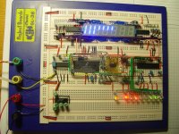
yulquen said:I have finally tested the VU-part of the TAS3103 on a breadboard-setup, and it works excellent!
Picture's...?
Member
Joined 2002
Member
Joined 2002
yulquen said:Picture of breadboard
nice wiring.
You should start building tube amps. 😀
- Status
- Not open for further replies.
- Home
- Source & Line
- Digital Line Level
- digital VU-meter