Going back through this amp to find the faults .
When looking the amp over I found this in the windings of 1 of the transformers .
Wondering will this cause any issues ?
Also wondering should I reflow them solder where the windings go through the board ?
When looking the amp over I found this in the windings of 1 of the transformers .
Wondering will this cause any issues ?
Also wondering should I reflow them solder where the windings go through the board ?
Attachments
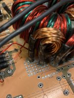
It won't hurt to solder it from the top but there are a lot of vias that are connecting the top and bottom of the board so it's not likely to be an issue unless the connection is intermittent on the bottom of the board.
Going back through this amp and noticed something . The diodes that connect to the drain leg of the power supply fets and to the 4148 diodes .
I have 36 volt zener diodes in there 1N4754 .
The schematic shows them as 39 volts .
Should I switch them out to what the schematic shows ?
some of the locations these are in
D31B,28B,31B
I have 36 volt zener diodes in there 1N4754 .
The schematic shows them as 39 volts .
Should I switch them out to what the schematic shows ?
some of the locations these are in
D31B,28B,31B
Nevermind I looked the value up on the net and it gave me the wrong voltage the diodes are correct
Back to this amp . I don’t get it .
the power supply will power up and idle fine . If I put the rectifiers back in the amp it will draw excessive current . I swapped out the rectifiers with know good ones and made sure they were in the right locations still no change with them in circuit the power supply board will draw excessive current
the power supply will power up and idle fine . If I put the rectifiers back in the amp it will draw excessive current . I swapped out the rectifiers with know good ones and made sure they were in the right locations still no change with them in circuit the power supply board will draw excessive current
Are the output FETs in the circuit?
Did you try installing one rectifier at a time to see if one rectifier or one polarity of rectifiers was causing the problem?
Are you using center-tapped rectifiers?
Did you try installing one rectifier at a time to see if one rectifier or one polarity of rectifiers was causing the problem?
Are you using center-tapped rectifiers?
The outputs are not in the amp I have the 2 boards separate right now . I’m working on the power supply board only .
The rectifiers im using are FMG36S/FMG36R
I tried installing them 1 at a time amp draws excessive current as soon as 1 is installed .
I tried a FMG36S in D19’s location amp will draw current took it back out and tried the FMG36R is F19’s location amp will still draw excessive current .
The rectifiers im using are FMG36S/FMG36R
I tried installing them 1 at a time amp draws excessive current as soon as 1 is installed .
I tried a FMG36S in D19’s location amp will draw current took it back out and tried the FMG36R is F19’s location amp will still draw excessive current .
Try this... The amp needs to be completely isolated, no connection to ANYTHING.
Connect your 12v power supply (with limiting resistor in series with it), across the positive rail caps. Be sure to get the polarity right. Do the positive rail caps charge to the 12v supply voltage?
Do the same with the negative rail caps (again, get the polarity right). Do they charge to the 12v supply voltage?
So just use the power wire with resistor to the rail caps nothing else connected to the amp .
If so the caps do not charge
If so the caps do not charge
Did you connect the ground wire to the cap negative?
What value resistor?
How much current draw when connected?
What value resistor?
How much current draw when connected?
I rechecked the rail caps .and yes the caps charge to 13 volts did this with the positive and negative rail caps
Under 'one' cap wouldn't cause the amp to draw excess current when the rectifier for the opposite rail was the only installed rectifier. There may be another cap on the other rail with the same problem.
Ok I repaired the board and got it to power up and idle fine put the 2 boards back together amp powers up and idles fine.
Amp is producing all the regulated voltages and both rail voltages . The outputs have rail to rail oscillation and the relays engage.
Amp has no audio .
Any ideas ?
Amp is producing all the regulated voltages and both rail voltages . The outputs have rail to rail oscillation and the relays engage.
Amp has no audio .
Any ideas ?
I give up on this amp either I’m gonna throw it away or sell it as is . I powered it back up and then one of the new rail caps started leaking electrolytic out the bottom of it
Not sure I measured it when I had no audio and the rail voltage was 145 the cap is rated at 200 volts . I shut the amp off and as soon as I powered it back up to check the voltages you asked for That’s when the cap started leaking
I removed 3 of the rail caps to clean the board 2 out of the 3 caps are still good .
with the 3 caps out I powered the amp up again and tested for audio the amp has output but very distorted
with the 3 caps out I powered the amp up again and tested for audio the amp has output but very distorted
- Home
- General Interest
- Car Audio
- Digital Designs Z2HV