Hello good day, I've been trying to locate what is causing a dc offset in channel 2 in my DD amplifier. Tried to contact DD for service manual etc, but got no response. Things that I've tried so far:
1) Checked all output transistors
2) Checked driver transistors
Has anyone worked on these amps and can share their experience? I'd be grateful for any advice.")
Note: When a speaker is connected to channel 2, the sound is distorted and when the volume is turned up the DC offset rises as well as the distortion. The other 3 channels are fine.
1) Checked all output transistors
2) Checked driver transistors
Has anyone worked on these amps and can share their experience? I'd be grateful for any advice.
Note: When a speaker is connected to channel 2, the sound is distorted and when the volume is turned up the DC offset rises as well as the distortion. The other 3 channels are fine.
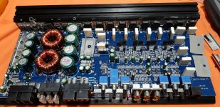
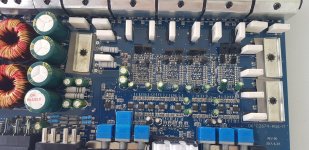
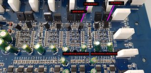
That sounds like only 1/2 of the output stage is driving. Post a photo of the entire board and another of the area showing the part of the board with the bad channel.
Do you have a scope?
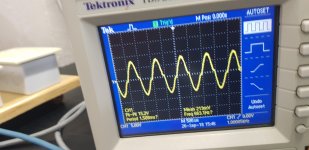
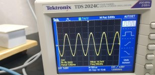
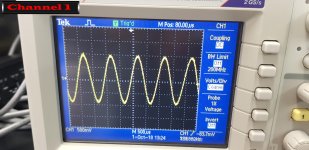
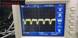
I don't really have a scope at home, but I did scoped the both channels in school with a constant 1khz tone and this is what I got. Channel 1 was a perfect Sinusoid while channel 2 had crossover distortion. The pictures are attached below.
Attachments
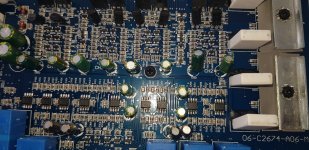
When i connect speakers, the music sounds distorted but words are audible. But I guess this is because of the DC offset. I measured and compared the drive transistor in channel 1 and compared it to channel 2. The base voltages are different, where do you think this can resonate from?
Attachments
Hi stark industries,
Perry is dead on target. Stick a 4 to 10 ohm, 5 or 10 watt resistor on both outputs. Don't turn the volume up yet! Apply enough signal to get a couple volts AC out and no more. Then connect the scope to each channel. You may find that the bad channel is missing most or all of one polarity of the waveform. If you have an open emitter resistor or output transistor, the driver can fill in the missing bit with no load. Once you load it, it's a completely different story. IF you aren't getting a clear enough output waveform then increase the signal level output, but not too much or you'll burn out the smaller load resistors, or cause the power supply to shut down (running off a smaller DC supply).
Taking measurements in the output section must be done with a different reference point other than "ground". Connect your (electrically floating) meter (-) lead to the output of that channel. Now you can make measurements that will make sense and be a lot more accurate. You can also use this connection to measure the resistance of the emitter resistors. Note that an open emitter resistor or open emitter-base connection may measure with about the expected voltage. To confirm these things are open you must measure the resistance of resistors, and use the diode check function to measure the junctions in BJT transistors. Mosfets are a little different. You would be looking for opens, or a resistive reading (means bad) out of circuit. Most enhancement Mosfets should masure open across all leads except for a reverse biased diode from drain to source.
Best, Chris
Hi stark industries,
Perry is dead on target. Stick a 4 to 10 ohm, 5 or 10 watt resistor on both outputs. Don't turn the volume up yet! Apply enough signal to get a couple volts AC out and no more. Then connect the scope to each channel. You may find that the bad channel is missing most or all of one polarity of the waveform. If you have an open emitter resistor or output transistor, the driver can fill in the missing bit with no load. Once you load it, it's a completely different story. IF you aren't getting a clear enough output waveform then increase the signal level output, but not too much or you'll burn out the smaller load resistors, or cause the power supply to shut down (running off a smaller DC supply).
Taking measurements in the output section must be done with a different reference point other than "ground". Connect your (electrically floating) meter (-) lead to the output of that channel. Now you can make measurements that will make sense and be a lot more accurate. You can also use this connection to measure the resistance of the emitter resistors. Note that an open emitter resistor or open emitter-base connection may measure with about the expected voltage. To confirm these things are open you must measure the resistance of resistors, and use the diode check function to measure the junctions in BJT transistors. Mosfets are a little different. You would be looking for opens, or a resistive reading (means bad) out of circuit. Most enhancement Mosfets should masure open across all leads except for a reverse biased diode from drain to source.
Best, Chris
Hey chris, thanks for the info. I'll test the outputs on the scope in school and post the results here.
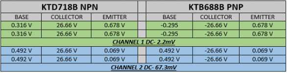
Below are the results from the test that I conducted today by attaching (2) 10 ohm 10 watt resistors to channels 1 & 2 at the amplifier’s terminals. Channel 1 is denoted in green color while channel 2 is denoted in blue. A 1khz signal was applied at a reasonable level to see an output on the scope’s screen, the pictures are posted below. I did not remove the transistors from the circuit to test them so the values above were measured with the loads connected with the signal raised at a reasonable level. The transistor type is above the respective table for each channel, also is the DC present in each channel. If there is anything I did incorrect please let me know.
Attachments
I changed all the output transistors (old ones were fine just placed new ones to ensure they were okay) , all driver transistors ( same as above) and checked all the emitter resistors(all were connected and working well). I also checked for bad solder connections( non present). The problem still exists, I'm not sure what I can do again anything I can do again Perry ?
The emitter legs are connected to the white power resistors that are 0.5 ohms each and when measured they all are the same. Also, there are 16 output transistors, so I think it's 4 per channel.( 2 NPN and 2 PNP ). From what I'm seeing is cross over distortion. Do you think the opamp can cause this ?
Yes, I read 1 ohm between all emitter legs.
The crossover distortion isn't the problem when the entire half of the signal is absent.
Do you read 1 ohm between all emitter legs of the 4 outputs for all channels?
I'm trying to determine the amp configuration.
- Status
- This old topic is closed. If you want to reopen this topic, contact a moderator using the "Report Post" button.
- Home
- General Interest
- Car Audio
- Digital Designs C4.100 150 mv Dc offset