Voltages appear to look correct..
Before putting new outputs in the amp check the following..
Check all the inductors/chokes..
They have a green body and the color bands are yellow purple black,, set your meter to diode check and test them they sould read 0.03 on diode check do you get any reading differnt then 0.03 ??
Also you must replace The Driver IC (IR21844S) that goes to the bank were u had a shorted output..
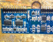
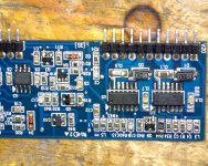
Also post a high res pic of the Audio driverboard again so I can see it and make sure you have all transistors and resistors in the right locations..
Before putting new outputs in the amp check the following..
Check all the inductors/chokes..
They have a green body and the color bands are yellow purple black,, set your meter to diode check and test them they sould read 0.03 on diode check do you get any reading differnt then 0.03 ??
Also you must replace The Driver IC (IR21844S) that goes to the bank were u had a shorted output..
Also post a high res pic of the Audio driverboard again so I can see it and make sure you have all transistors and resistors in the right locations..
I'm trying to take a good pictures with my camera,(Sony 10.1 mp)
But after many pictures, non will show the value of
The components. Can any one suggest me a good camera
The I can use for this, I don't mind buying it, I need it any way.
Thanks in advance.
But after many pictures, non will show the value of
The components. Can any one suggest me a good camera
The I can use for this, I don't mind buying it, I need it any way.
Thanks in advance.
The basic repair page shows clear photos taken with a 2MP camera. Your camera can likely do it as well. Does it have a macro mode?
What is the exact make/model of the camera?
What is the exact make/model of the camera?
Digital Cameras, Sony Cyber-shot DSC-W170 Digital Camera Test Image
It seems to be fairly good. That's a macro sample. View it full size to see how much detail it captured.
It seems to be fairly good. That's a macro sample. View it full size to see how much detail it captured.
After replacing all 4 driver ICs and checking all components one by one
I re solder the driver board back to the amp.
Using the scope I'm getting signal on 8 of the 16 transistors gates, the first 4 and the last 4 of every shoulder Have no signal, also the duty cycle looks like 40% ON 50% OFF.
Please see picture.
I re solder the driver board back to the amp.
Using the scope I'm getting signal on 8 of the 16 transistors gates, the first 4 and the last 4 of every shoulder Have no signal, also the duty cycle looks like 40% ON 50% OFF.
Please see picture.
Attachments

I don't think so. Do you see a 2kHz signal on any of the legs of the muting transistor?
Do you see any signal on any of the other pads for the output transistors?
Do you see any signal on any of the other pads for the output transistors?
There are 16 transistor on every shoulder, The 1st 4 MOSFET don't
Have signal, The next 8 MOSFET have the 2 kHz signal and the last
4 MOSFET don't Have signal, Same thin for both shoulder.
Have signal, The next 8 MOSFET have the 2 kHz signal and the last
4 MOSFET don't Have signal, Same thin for both shoulder.
This signal is only on the gate pad for the transistor locations that have signal. Is that correct?
Isn't pin 9 the negative rail?
From the photo you posted, it appears that the amp has only 16 output transistors. If only half of the output transistors have signal, how can you get 16 transistors that have signal on the gate pads?
From the photo you posted, it appears that the amp has only 16 output transistors. If only half of the output transistors have signal, how can you get 16 transistors that have signal on the gate pads?
- Status
- Not open for further replies.
- Home
- General Interest
- Car Audio
- Digital design