I have a Digital Design M1d in front on me right now. It came to me already disassembled and I was looking it over. I noticed on the PWM board for the power supply section has a missing 22uf 16v SMD can cap (c18) on the PWM board p/n SOB-004-70. 2009.09 rev:0
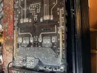
So I pulled slid the main board from the heat sink to see if I could find the missing cap and check if the PWM board showed signs of having been pulled before. It doesn’t look as though it has, so I don’t know if the PWM never had that cap or if it fell off somehow.
The other thing I noticed these trace bridges on the bottom of the circuit board where the power supply mosfets are soldered to the board. I have attached a photo. Is this factory or something else? I haven’t worked on many DD amps so I’m not sure what to make if it.
Attachments
Well they look dull and smooth to me and appear to have solder on the pads. I have seen power supply caps get so hot that the de-solder themselves and start rattling around inside the amp. So I wasn’t sure. I can’t find the cap anywhere in the amp, but the amp was already taken apart before I came in possession of it, so it may have been lost. I’ll bring it up on low power and limited current and see what happens.
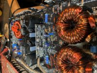
Okay. So the amp powered up fine under low voltage and limited current and no smoke or heating. The relay clattered a little at first. So I brought it up on 14 volts and no current limit and the amp powered up fine. Nice big square wave is being produced in the high side drive. The Power supply looks healthy, with nice square waves on the tabs of all the mosfets.
So it would appear that my observations earlier are normal for this amp.
I connected RCAs and a speaker and I get no audio output so now I’m off to troubleshoot that area of the board.
So it would appear that my observations earlier are normal for this amp.
I connected RCAs and a speaker and I get no audio output so now I’m off to troubleshoot that area of the board.
Thanks for clearing that up for me Perry.
As for the no audio. I checked DC offset and it within tolerance .023 volts. I check the regulated voltage at the opamp TL072 and I get +15 volts and -15 volts and 30 volts across the opamp. So that’s all good. Now I’m checking the output of the relay to see if anything is going on there.
As for the no audio. I checked DC offset and it within tolerance .023 volts. I check the regulated voltage at the opamp TL072 and I get +15 volts and -15 volts and 30 volts across the opamp. So that’s all good. Now I’m checking the output of the relay to see if anything is going on there.
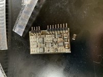
I was tracing the signal that I was feeding into the board and I shorted out this diode on the output card and I can’t identify this diode to save my life. Does anyone have a clue or educated guess or whatever. I’m getting nowhere fast. I’ve attached a picture. It is marked 8852. It is located next to the terminal pins.
Attachments
I was tracing the signal that I was feeding into the board and I shorted out this diode on the output card and I can’t identify this diode to save my life. Does anyone have a clue or educated guess or whatever. I’m getting nowhere fast. I’ve attached a picture. It is marked 8852. It is located next to the terminal pins.
It's not a critical part, as far as specs are concerned. It needs to be able to easily withstand full rail-rail voltage and have a fast recovery. The ES1G is commonly used in larger amps.
If you shorted that diode, the high-side of the IC may have been damaged, It's a fragile IC.
If you shorted that diode, the high-side of the IC may have been damaged, It's a fragile IC.
Well I had shorted that board trying to trace the signal in my early troubleshooting of this amp. The amp would come up but had no sound. I thought it prudent to go ahead and change them before I put the board back into the amp.
Are there certain components to look for or a board component layout that helps in determining between tl072s or 4558s or what not?
Thanks for the help,
David
Are there certain components to look for or a board component layout that helps in determining between tl072s or 4558s or what not?
Thanks for the help,
David
The components won't generally indicate what the 8-pin IC is except for having a pull-up resistor on an output terminal. That's GENERALLY limited to comparators but I have seen it on op-amps in some amps.
If you think the board has problems, you can install it on jumper wires to operate the amp with the board where you can get to all of the terminals of all of the components.
If you think the board has problems, you can install it on jumper wires to operate the amp with the board where you can get to all of the terminals of all of the components.
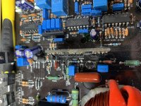
Can anyone tell me what diode belongs in the position marked D204. I can’t magnify it enough to read the code printed on it. It is in parallel with a 10uf 16volt bipolar cap that I also removed from the board (C11B) because it tested shorted but it was actually the Diode that had turned itself into a jumper.
I was thinking of replacing it with a 4148.
David
I was thinking of replacing it with a 4148.
David
Attachments
Ok. I replaced the shorted zenner with a 4148 zenner and took some voltage measurements.
The amp powers up with a green LED and produces rail voltage but no audio passes through the amp.
The output driver card has a row of 8 pins and a gap and then a row of 4 pins. I started at the row of 8 pins and the pin on the outside edge I’m calling pin 1.
1. -70.8
2. -70.8
3. -70.9
4. -70.8
5. 0.002
6. 0.002
7. 13.14
8. 0.002
9. 0.002
10. 0.002
11. -15.9
12. +15.8
- Status
- This old topic is closed. If you want to reopen this topic, contact a moderator using the "Report Post" button.
- Home
- General Interest
- Car Audio
- Digital Design M1d